Explanation Direct Memory Access and ADC example with DMA
Hello everyone, We are going to talk about what is DMA which stands for Direct Memory Accessing and how can we configure it on ARM based STM microcontrollers with an example on ADC.Now it is time to start to talk.
The term DMA stands for Direct Memory Access. So you can access the memory or value of any periphal adress and transfer some datas between them. DMA allows the developer to move data between register adresses. We will use the ARM based microprocessor STM32F429ZI. Producers generally recommend to use DMA for I2C and SPI transferring due to keep the data in safe.
Another major specification of DMA is: DMA can transfer data during the processor is working on another task. We can think it as an independent seperate processor. DMA is transferring taha from directly the base adress to the target adress directly. And it is a seperate layer for this task and do not need the CPU.
- Periphal to Memory
- Memory to Periphal
- Memory to Memory
Lets talk about DMA on an example now. We are going to built a program to read Analog voltages on ADC with DMA on STM32F429ZI with STD Periphals.
- Framework
- ADC
- GPIO
- RCC
- DMA
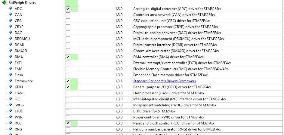
Before to start the example first we specify the periphals to enable.
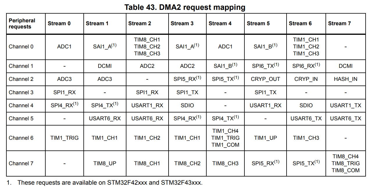
We will use the ADC1 to read analog voltage. ADC1 IN0 channel connected to GPIOA Pin0. Also ADC1 periphal connected to DMA2. Below tables you can see the STM32F4 DMA mapping tables. It is important to check below tables before to start coding. As youcan see the below table every periphal connected to a DMA channel. ADC1 IN0 channel is connected to DMA2 Channel0 Stream0.
	//Enable Required Buses
	RCC_AHB1PeriphClockCmd(RCC_AHB1Periph_GPIOA, ENABLE);
	RCC_APB2PeriphClockCmd(RCC_APB2Periph_ADC1, ENABLE);
	RCC_AHB1PeriphClockCmd(RCC_AHB1Periph_DMA2, ENABLE);
//GPIO structure to config the GPIO pins
GPIO_InitTypeDef GPIO_InitStructure;
//DMA structure to config DMA
DMA_InitTypeDef DMA_InitStructure;
//ADC cong structures to set ADC configurations
ADC_InitTypeDef ADC_InitStructure;
ADC_CommonInitTypeDef ADC_CommonInitStructure;
uint16_t ADC1_CH0_Value = 0;
//ADC1 IN0 connected to PA0 Pin
GPIO_InitStructure.GPIO_Mode = GPIO_Mode_AIN;
GPIO_InitStructure.GPIO_Pin = GPIO_Pin_0;
GPIO_InitStructure.GPIO_Speed = GPIO_Speed_50MHz;
GPIO_InitStructure.GPIO_OType = GPIO_OType_PP;
GPIO_InitStructure.GPIO_PuPd = GPIO_PuPd_NOPULL;
//Activate the GPIO configurations
GPIO_Init(GPIOA, &GPIO_InitStructure);
ADC_CommonInitStructure.ADC_Mode = ADC_Mode_Independent; // We set the ADC Mode as Independent to work.
ADC_CommonInitStructure.ADC_Prescaler = ADC_Prescaler_Div4; // We have set the prescaler value. Received data will bi divided by 4.
ADC_CommonInit(&ADC_CommonInitStructure); //Started the above configurations.

ADC_InitStructure.ADC_Resolution = ADC_Resolution_8b; // this means we are going to divide the value by 20mV.
ADC_InitStructure.ADC_ScanConvMode = DISABLE;
ADC_InitStructure.ADC_ContinuousConvMode = ENABLE;
ADC_InitStructure.ADC_ExternalTrigConvEdge = ADC_ExternalTrigConvEdge_None;
ADC_InitStructure.ADC_ExternalTrigConv = ADC_ExternalTrigConv_T1_CC1;
ADC_InitStructure.ADC_DataAlign = ADC_DataAlign_Right;
ADC_InitStructure.ADC_NbrOfConversion = 1;
ADC_Init(ADC1, &ADC_InitStructure); //Set configuration of ADC1

//Enable ADC1
ADC_Cmd(ADC1, ENABLE);
	DMA_InitStructure.DMA_Channel = DMA_Channel_0;
	DMA_InitStructure.DMA_PeripheralBaseAddr = (uint32_t) &ADC1->DR;
	DMA_InitStructure.DMA_Memory0BaseAddr = (uint32_t) &ADC1_CH0_Value;
	DMA_InitStructure.DMA_DIR = DMA_DIR_PeripheralToMemory;
	DMA_InitStructure.DMA_BufferSize = 2;
	DMA_InitStructure.DMA_PeripheralInc = DMA_PeripheralInc_Disable;
	DMA_InitStructure.DMA_MemoryInc = DMA_MemoryInc_Disable;
	DMA_InitStructure.DMA_PeripheralDataSize = DMA_PeripheralDataSize_HalfWord;
	DMA_InitStructure.DMA_MemoryDataSize = DMA_MemoryDataSize_HalfWord;
	DMA_InitStructure.DMA_Mode = DMA_Mode_Circular;
	DMA_InitStructure.DMA_Priority = DMA_Priority_High;
	DMA_InitStructure.DMA_FIFOMode = DMA_FIFOMode_Disable;
	DMA_InitStructure.DMA_FIFOThreshold = DMA_FIFOThreshold_HalfFull;
	DMA_InitStructure.DMA_MemoryBurst = DMA_MemoryBurst_Single;
	DMA_InitStructure.DMA_PeripheralBurst = DMA_PeripheralBurst_Single;
	//here we select the DMA Stream to use
	DMA_Init(DMA2_Stream0, &DMA_InitStructure);
	//Here we start the related DMA
	DMA_Cmd(DMA2_Stream0, ENABLE);
Now I will explain the important configuration variables one by one:
DMA_Channel : With this configuration we are setting the which channel we will use. As I mentioned at head of the article every periphal connected to a DMA, channel and streams.
uint16_t ADC_GetConversionValue(ADC_TypeDef* ADCx)
{
  /* Check the parameters */
  assert_param(IS_ADC_ALL_PERIPH(ADCx));
  /* Return the selected ADC conversion value */
  return (uint16_t) ADCx->DR;
}
DMA_Memory0BaseAddr: We will specify the target adress. In this example I define a variable at the head of program and I will keep the ADC values on this variable.
DMA_DIR: This configuration specifies the direction of data transferring. We will transfer the datas from ADC1 periphal to the memory. So we set it as DMA_DIR_PeripheralToMemory
DMA_BufferSize: This variable specify the how many bytes to transfer
DMA_PeripheralDataSize: Meriphal Data size
DMA_MemoryDataSize: Memory Data Size
- Circular Mode : DMA starts again when its task completed and transfered data count which specified in buffer size.
- Normal Mode : DMA stops when the task is completed.
DMA_Priority: Specify the priority of the DMA process.
DMA_FIFOMode: FIFO Mode. This configuration requires more settings.
Here we have built a program to read analog voltage from ADC with DMA. You probably can not see the value updating on the Debug watcher . I also could not :D. You can use below method to see is it working or not. Below code block is a simple LED blinking method. it is blinking the led and delay a period which is equal to the ADC value multiplied by 50000. When the Analog voltage decreases led will blink faster and voltage value increase LED blink slowly.
	while(1)
	{
		int delaytime = ADC1_CH0_Value * 50000;
		GPIO_SetBits(GPIOB, GPIO_Pin_0);
		while(delaytime ) delaytime --;
		GPIO_ResetBits(GPIOB, GPIO_Pin_0);
		while(delaytime ) delaytime --;

	}
You do not need to create any function in while loop or any IRQ handler to read Adc voltage value now. In this way DMA will transfer the value from ADC->DR to the related variable.
That is all in this article. Now you are ready to use ADC with DMA on STM32F4 Std periph.
Have a nice Direct Memory Accessing.
Burak Hamdi TUFAN.
Tags
Share this Post
Author

I am a software developer experienced 15 years and here to share all my programming experiences. I have worked on so many platforms and programming languages especially C, C#, C++ and Java. I am studing PhD at Kocaeli University on Aviation Technologies. I am building softwares and technologies on aviation.


Comments