Position Control of DC Motor with STM32F4 PWM and PID
Hello everyone,In this article we will talk about Position control of a DC motor. If you read part1 of this article you will your motor will be move so fast and probably will miss the set value. Now will will set the speed of the motor and our motor will be moved at efficient speed and we will let the motor to catch up the best rotation speed.You can reach the below article from here https://thecodeprogram.com/position-control-of-dc-motor-with-stm32f4-stdperiph. I strongly recommend to read that article if you did not, because I explained so many things in previous article.
And also I recommend to look at this article, you can see how to create PWM signal with STM32F4 TIM hardware. https://thecodeprogram.com/stm32f4-timers-and-pwm-generation-with-std-periph
Now let's get started and get this done.
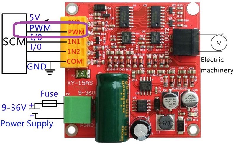
We are going to set a PWM output with TIM hardware on STM32F4 and we will connect this PWM output to the PWM input of the motor driver. Below image you can seew the PWM input of the DC motor driver.
We will also make a calculation with Timer Interrupts. This will save time in our program, and in will make some calculations in a decided times. So we will need a NVIC Structure variable to activate TIMER interrupts.
GPIO_InitTypeDef      GPIO_InitStruct;
TIM_TimeBaseInitTypeDef TIM_TimeBaseInitStructure;
TIM_OCInitTypeDef           TIM_OCStruct;
NVIC_InitTypeDef NVIC_InitStructure;
Now we will make configurations of them:
RCC_AHB1PeriphClockCmd(RCC_AHB1Periph_DMA2 | RCC_AHB1Periph_GPIOC | RCC_AHB1Periph_GPIOA | RCC_AHB1Periph_GPIOD, ENABLE);
RCC_APB2PeriphClockCmd(RCC_APB2Periph_ADC2, ENABLE);
//TIM2 will be used for NVIC
//TIM4 will be used for PWM output
RCC_APB1PeriphClockCmd(RCC_APB1Periph_TIM2 | RCC_APB1Periph_TIM4, ENABLE);
//We set the pin mode for Alternate Function
GPIO_InitStruct.GPIO_Mode = GPIO_Mode_AF;
GPIO_InitStruct.GPIO_OType = GPIO_OType_OD;
GPIO_InitStruct.GPIO_Pin = GPIO_Pin_12;
GPIO_InitStruct.GPIO_PuPd = GPIO_PuPd_UP;
GPIO_InitStruct.GPIO_Speed = GPIO_Speed_100MHz;
//Initialize the pin
GPIO_Init(GPIOD, &GPIO_InitStruct);

//Assignment the pin as TIM4 Alternate Function
GPIO_PinAFConfig(GPIOD, GPIO_PinSource12, GPIO_AF_TIM4);
And now first I will configure the NVIC firstly.
Below code block will prepare the TIM2 and NVIC. I have used this code block on my PID controller project to calculate the PID value between my sensr value and potantiometer value. So it will create a alue and my pwm will be it. Result of this DC motor will stop to make oscilositions and it will rotate at precision speed. I will share just Proportional stage of the PID function in this article. Forgive me :)
//Configure TIM2 to calculate PID -------------------------------------------------------------------
	TIM_TimeBaseInitStructure.TIM_Prescaler = 4199;
	TIM_TimeBaseInitStructure.TIM_CounterMode = TIM_CounterMode_Up;
	TIM_TimeBaseInitStructure.TIM_Period = 2000;
	TIM_TimeBaseInitStructure.TIM_ClockDivision = TIM_CKD_DIV4;
	TIM_TimeBaseInitStructure.TIM_RepetitionCounter = 50;
	TIM_TimeBaseInit(TIM2, &TIM_TimeBaseInitStructure);
	TIM_Cmd(TIM2, ENABLE);
	TIM_ITConfig(TIM2, TIM_IT_Update, ENABLE);
	//Configure NVIC to calculate PID --------------------------------------------------------------------
	NVIC_InitStructure.NVIC_IRQChannel = TIM2_IRQn;
	NVIC_InitStructure.NVIC_IRQChannelPreemptionPriority = 0x00;
	NVIC_InitStructure.NVIC_IRQChannelSubPriority = 0x01;
	NVIC_InitStructure.NVIC_IRQChannelCmd = ENABLE;
	NVIC_Init(&NVIC_InitStructure);
	//---------------------------------------------------------------------------------------------------
//Interrupt handler of the TIM2 NVIC, this function will run function  to calculate PWM value.
void TIM2_IRQHandler()
{
	if(TIM_GetITStatus(TIM2, TIM_IT_Update) == SET) //check the TIMER is active
	{
		//always reset the interrupt
		TIM_ClearITPendingBit(TIM2, TIM_IT_Update);
		MOTOR_1_PID_PWM = fnc_calculatePID(ADCValues[1], ADCValues[0]);
	}
}

//this example function will calculate the precision speed value. In here just Proportional variable is enough for this DC motor.
uint16_t fnc_calculatePID(long _sensor_position, long _desired_position)
{
	error_value = _desired_position - sensor_position;
	output_value = error_value * 0.4;

	return output_value < 0 ? (output_value  * (-1)) : output_value ;
}
TIM_TimeBaseInitTypeDef TIM_BaseStruct;
TIM_BaseStruct.TIM_Prescaler = 0;

TIM_BaseStruct.TIM_CounterMode = TIM_CounterMode_Up;

TIM_BaseStruct.TIM_Period = 17999;
TIM_BaseStruct.TIM_ClockDivision = TIM_CKD_DIV1;
TIM_BaseStruct.TIM_Prescaler = 1;
TIM_BaseStruct.TIM_RepetitionCounter = 0;

TIM_TimeBaseInit(TIM4, &TIM_BaseStruct);
TIM_Cmd(TIM4, ENABLE);

TIM_OCInitTypeDef TIM_OCStruct;

TIM_OCStruct.TIM_Pulse = 9999;
TIM_OC1Init(TIM4, &TIM_OCStruct);
TIM_OC1PreloadConfig(TIM4, TIM_OCPreload_Enable);
After PWM initialization we need to set the DC motor rotation direction and make rotations at correct direction.
You are familiar with below code block from previous article. I just added the pwm configurations. As I mentioned above I calculated the PWM with PID functions' proportional stage. May bee you do not need to use Integral and derivative parts maybe you will need, I do not know you requirements :).
    while(1)
    {
			if(ADCValues[0] < ADCValues[1]) fnc_rotateLeft();
			else if(ADCValues[0] > ADCValues[1]) fnc_rotateRight();
			else fnc_rotateStop();

			VAL_TIM_PWM = fnc_scale(MOTOR_1_PID_PWM,0,255,0,MAX_PWM_VAL);
			TIM4->CCR1 = VAL_TIM_PWM;

    }
That is all in this article.
Have a good DC motor controlling.
Burak hamdi TUFAN.
Tags
Share this Post
Author

I am a software developer experienced 15 years and here to share all my programming experiences. I have worked on so many platforms and programming languages especially C, C#, C++ and Java. I am studing PhD at Kocaeli University on Aviation Technologies. I am building softwares and technologies on aviation.
Comments