ADS1115 with STM32 CubeMx
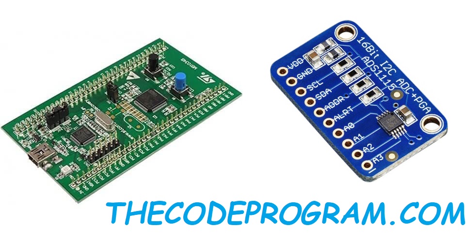

ADS1115 is an analog to digital converter (ADC). It is ultra small sized and has I2C communication. It has 4 channels to read analog voltages and transmit these voltage values via I2C communication bus. For more details you can check datasheet of ADS1115.
Now lets start with a cubemx project and configure board for ADS1115 and I2C communication. My processor is STM32F051R8T6 and I have created project with this microprocessor.

After creating new cubemx project we need to acticate I2C under Connectivity section. PB7 as SDA and PB6 as SCL pin will be activated. On the left panel in parameter Above image have all my I2C parameter settings. I did not activated NVIC because I will do send and receive. This means I will send data and according to this ADS1115 will send requested datas. So just activate I2C and set parameter like above. Do not activate NVIC and DMA for this process.
If we are ready to start we must generate code now.
First we need to declare necessary variables.
//Connect ADDR pin to GND and I2C slave adress will be 0X48 .
#define ADS1115_ADDRESS 0x48
unsigned char ADSwrite[6];
int16_t reading;
float voltage[4];
const float voltageConv = 6.114 / 32768.0;
We are gonna use these variables to read voltage values from ADS1115.
Now we need to insert below code block into while section.
for(int i=0; i< 4; i++){
			ADSwrite[0] = 0x01;

			switch(i){
				case(0):
					ADSwrite[1] = 0xC1; //11000001
				break;
				case(1):
					ADSwrite[1] = 0xD1; //11010001
				break;
				case(2):
					ADSwrite[1] = 0xE1;
				break;
				case(3):
					ADSwrite[1] = 0xF1;
				break;
			}

			ADSwrite[2] = 0x83; //10000011 LSB

			HAL_I2C_Master_Transmit(&hi2c1, ADS1115_ADDRESS << 1, ADSwrite, 3, 100);
			ADSwrite[0] = 0x00;
			HAL_I2C_Master_Transmit(&hi2c1, ADS1115_ADDRESS << 1 , ADSwrite, 1 ,100);
			HAL_Delay(20);

			HAL_I2C_Master_Receive(&hi2c1, ADS1115_ADDRESS <<1, ADSwrite, 2, 100);
			reading = (ADSwrite[0] << 8 | ADSwrite[1] );
			if(reading < 0) {
				reading = 0;
			}
			voltage[i] = reading * voltageConv;

		}
As you can see there is a for loop top of code. This for loop looking for 4 values. We are choosing which channel to read in this for loop. 0xC0, 0xD0, 0xE0 and 0xF0 values provided from datasheet. These values are for selecting to channel. Last value of the sended variable is for choosing LSB or MSB. If we want get value as reversed. After specifing the read configurations we need to transmit this variable into I2C data bus and ADS1115 will read this values. After this ADS1115 will answer to our microprocessor. Then receive the answer.
Then multiply the value with voltage conversation constant and get the between 0 - 5 voltage value.
You are ready for reading ADS1115 now. We can make this with all series stm32. If you want to do this STM32F4 processors you are free to do this.
That is all for this post now.
Burak Hamdi TUFAN