 Hello everyone, in this article we are going to talk about Analog to Digital Converters. We will talk about what they are first and then what kind of ADC's exist and where can we find them.
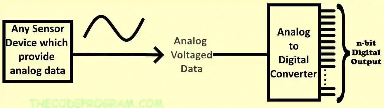
In universe every data is provide values as analog datas. But not every computer get and process them as analog data. Computers understand and process on digital values. So we need to convert the analog datas to the digital datas. In this case we are in need of assistance of Analog to Digital Converters.
ADC's are using almost every fields in the world such as power control systems, communicating, measurement devices, energy systems automation, aerospace... The ADC devices always assist the engineers to understand and process the environmental values like heat, distance, speed, RPM, quantity.
So, How ADC works
Analog to Digital Converter circuits has an input for analog voltage. This analog voltage is being processed via logical circuits and produce a binary output according to input voltage and resolution.
Below image you can see a simple schematic of ADC Integrated Circuits.
ADC get the sample values from the analog input voltage at every clock signal according to resolution. The ADC device can produce an average value of multiple samples or produce the digital binary value according to input voltage. It depends on the type and resolution of the ADC device.
The resolution of an ADC delegates with its bit rate. The bitrate express that the bit quantity to specify the voltage level. The ADC device divides the input voltage to the bit rate and produce an output according to prepared binary value.
For example think about a
0V-5V and
4-bit ADC.
- Our resolution : 2^4 = 16.
- Our Referance voltage is 5V.
- Instant voltage is : n
- Result is:
- Every 1V will be expressed with 16/5V
- n Voltage will be expressed with (16/5V) * n
- If we say n=3V digital output will be (16/5V) * 3V = 9,6
When we increase the bit rate of the ADC device, it will produce more sensitive results.
Some of Common Analog to Digital Conversion Methods :
Flash ADC
This type of ADC is most commonly used ADC. This type of ADC also known as Paralel ADC. Because these ADC's are working simultaneously and no need a clock signal or external processor. According to this specification, this type of ADC's are fastest types of Analog to Digital Conversation. It produce the digital output instantly according to analog value.
Comparators are using in this type f method. Inputs of comparators are a divided Vref by bit-rate quantity resistors and input signal. At all ladder point the Vref voltage is being divided by two and the comparator compare them with input voltage value.
Below image you can see the basic schematic.
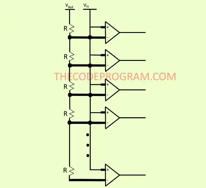
This type of ADC's are
realy realy fast but it has some minus specifications:
- These ADC's have 2n-1 comparators for n-bit resolution conversation. So every bit increasing require dounle quantity components and it sizes very much.
- This type of ADC consumes co much power because it has so many comparators and resistors.
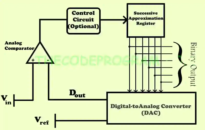
Successive Approximation (SAR) ADC
This type of ADC has an input, a Digital-to-Analog converter, an analog comparator, a Succesive Approximation Register (SAR). When SAR ADC initialized the MSB bit be HIGH. And a digital code produced from register. This code will be sent to DAC to produce a analog equilevant of the code to make a comparisation in an analog comparator. If this analog voltage is more than Vin voltage value it will set the related bit as LOW. Otherwise it will remain as HIGH. The ADC will make this operation for all bits in the register. And we can get the binary value of the analog voltage from the Succesive Approximatin registers' bits.
- Input : Get and hold the Vin voltage for the processing.
- Successive Approximation Register : It produce approximate digital value for the internal Digital-to-Analog converter.
- Internal Digital-to-Analog Converter : It supplies the analog value of the digital code which got from SAR circuit.
- Analog comparator : It make a comparisation between Vref voltage and output voltage of DAC which produced according to digital code from SAR.
Below image you can see the simple schematic of the SAR ADC:
That is all in this article.
Have a good analog-to-digital converting.
Tags
Author
Burak Hamdi TUFAN
I am a software developer experienced 15 years and here to share all my programming experiences. I have worked on so many platforms and programming languages especially C, C#, C++ and Java. I am studing PhD at Kocaeli University on Aviation Technologies. I am building softwares and technologies on aviation.


Comments