Position Control of DC Motor with STM32F4 StdPeriph
Hello everyone, in this article we are going to talk about position controlling of a DC motor with a potantiometer in STM32F4 and Std periph Driver library. I will use the STM32F429ZI-Nucleo developer board.Firstly I want to talk about what exactly we will do in this example.
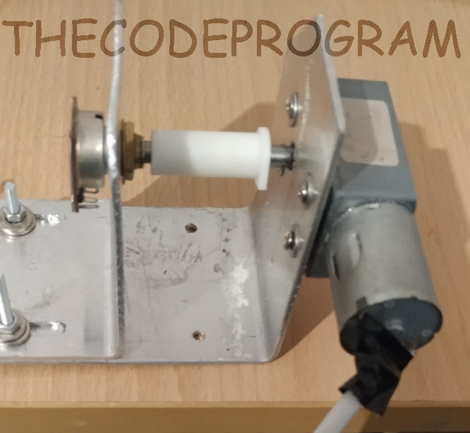
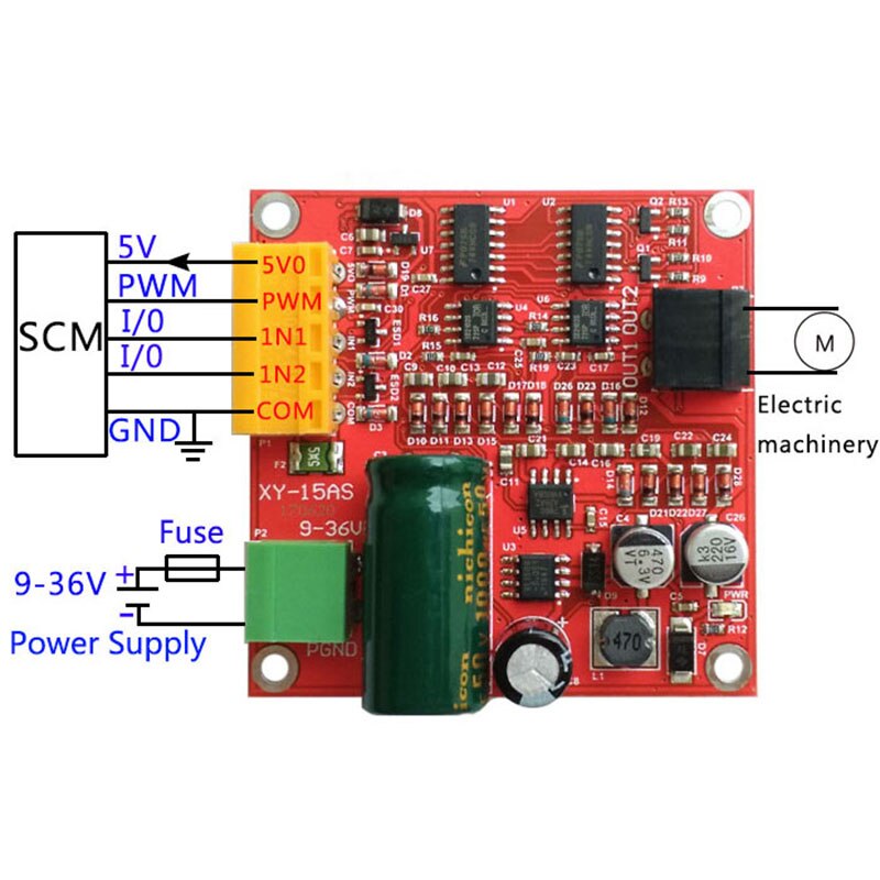
I have a DC motor and a H_Bridge DC motor driver. I also linked a potansiometer and this DC motor by their rotational parts. So I let the potansiometer to rotate when the DC motor rotated. I will connect this potansiometer to my microcontrollers' Analog to Digital converter pin. I will read the voltage level of this potansiometer and result of the potansiometers value I will decide the position of the DC motor.
I also will use the DMA channel of the ADC and I will make some calculations. To decide the angle value of the DC motor.

I want to tell what I have done now in this example :
I have got two potantiometers, we will use the one of them to set the angle value of the motor rotation. The other potantiometer will be connected to the DC motor. This potantiometer will measure the rotation angle of the motor.
We always try to make them equal. In another projects you can set this setting value from the the USART, CAN or SPI etc...
First we will read both analog values with DMA on ADC. We are going to use multi channel ADC reading with DMA. I have talked about it on this link.
uint16_t ADCValues[2] = {0,0};

    GPIO_InitTypeDef      GPIO_InitStruct;
    DMA_InitTypeDef       DMA_InitStruct;
    ADC_InitTypeDef       ADC_InitStruct;
    ADC_CommonInitTypeDef ADC_CommonInitStruct;

    // Enable related clock buses
    RCC_AHB1PeriphClockCmd(RCC_AHB1Periph_DMA2 | RCC_AHB1Periph_GPIOC | RCC_AHB1Periph_GPIOA | RCC_AHB1Periph_GPIOD, ENABLE);
    RCC_APB2PeriphClockCmd(RCC_APB2Periph_ADC2, ENABLE);//ADC2 is connected to the APB2 peripheral bus

    //We will set the channel as DMA_Channel_1
    DMA_InitStruct.DMA_Channel = DMA_Channel_1;
    //We will set the source as ADC2s' Data and memory ADCValues
    DMA_InitStruct.DMA_PeripheralBaseAddr = (uint32_t)&ADC2->DR;
    DMA_InitStruct.DMA_Memory0BaseAddr = (uint32_t)&ADCValues;
    //Set the direction as Periphal to Memory
    DMA_InitStruct.DMA_DIR = DMA_DIR_PeripheralToMemory;
    //We will use 6 adc channel. and buffer size is 2
    DMA_InitStruct.DMA_BufferSize = 2;
    DMA_InitStruct.DMA_PeripheralInc = DMA_PeripheralInc_Disable;
    DMA_InitStruct.DMA_MemoryInc = DMA_MemoryInc_Enable;
    //We will set data sizes as 16-bit
    DMA_InitStruct.DMA_PeripheralDataSize = DMA_PeripheralDataSize_HalfWord;
    DMA_InitStruct.DMA_MemoryDataSize = DMA_MemoryDataSize_HalfWord;
    //DMA circular mode enables the dma to start when it is done
    DMA_InitStruct.DMA_Mode = DMA_Mode_Circular;
    DMA_InitStruct.DMA_Priority = DMA_Priority_High;
    DMA_InitStruct.DMA_FIFOMode = DMA_FIFOMode_Disable;
    DMA_InitStruct.DMA_FIFOThreshold = DMA_FIFOThreshold_HalfFull;
    DMA_InitStruct.DMA_MemoryBurst = DMA_MemoryBurst_Single;
    DMA_InitStruct.DMA_PeripheralBurst = DMA_PeripheralBurst_Single;
    //Initialize the DMA
    DMA_Init(DMA2_Stream2, &DMA_InitStruct);
    //Enable the DMA
    DMA_Cmd(DMA2_Stream2, ENABLE);

    //Configure the related pins to read analog voltage.
    //So we will set the pin mode as Analog ınput
    GPIO_InitStruct.GPIO_Pin = GPIO_Pin_0 | GPIO_Pin_1 ;
    GPIO_InitStruct.GPIO_Mode = GPIO_Mode_AIN;
    GPIO_InitStruct.GPIO_PuPd = GPIO_PuPd_NOPULL ;
    //Initialize the related pins
    GPIO_Init(GPIOC, &GPIO_InitStruct);


    ADC_CommonInitStruct.ADC_Mode = ADC_Mode_Independent;
    ADC_CommonInitStruct.ADC_Prescaler = ADC_Prescaler_Div2;
    ADC_CommonInitStruct.ADC_DMAAccessMode = ADC_DMAAccessMode_Disabled;
    ADC_CommonInitStruct.ADC_TwoSamplingDelay = ADC_TwoSamplingDelay_5Cycles;
    ADC_CommonInit(&ADC_CommonInitStruct);

    ADC_DeInit();
    ADC_InitStruct.ADC_Resolution = ADC_Resolution_8b;
    ADC_InitStruct.ADC_ScanConvMode = ENABLE;
    ADC_InitStruct.ADC_ContinuousConvMode = ENABLE;
    ADC_InitStruct.ADC_ExternalTrigConv = 0;
    ADC_InitStruct.ADC_ExternalTrigConvEdge = ADC_ExternalTrigConvEdge_None;
    ADC_InitStruct.ADC_DataAlign = ADC_DataAlign_Right;
    ADC_InitStruct.ADC_NbrOfConversion = 2;
    ADC_Init(ADC2, &ADC_InitStruct);

    ADC_RegularChannelConfig(ADC2, ADC_Channel_10, 1, ADC_SampleTime_144Cycles);//PC0
    ADC_RegularChannelConfig(ADC2, ADC_Channel_11, 2, ADC_SampleTime_144Cycles);//PC1


    ADC_DMARequestAfterLastTransferCmd(ADC2, ENABLE);
    ADC_DMACmd(ADC2, ENABLE);
    ADC_Cmd(ADC2, ENABLE);
    ADC_SoftwareStartConv(ADC2);
Now our analog voltages will bwe transferred into the ADCValues array and will be kept in that array. After that we will set our while loop to decide the rotation direction and set the pin HIGH or LOW. I have three functions to rotateLeft, rotateRight and stop. The DC motor driver which I used make combinations with the IN1 and IN2 values. When one of them HIGH and the other one is LOW it will rotate to a direction when you reversed it it will reverse the motor.
//function to rotate motor to the left side
void fnc_rotateLeft()
{
	GPIO_SetBits(GPIOD, GPIO_Pin_12);
	GPIO_ResetBits(GPIOD, GPIO_Pin_13);
	fnc_waitCycle(10000);
}
//function to rotate motor to the right side
void fnc_rotateRight()
{
	GPIO_ResetBits(GPIOD, GPIO_Pin_12);
	GPIO_SetBits(GPIOD, GPIO_Pin_13);
	fnc_waitCycle(10000);
}
//function to stop motor
void fnc_rotateStop()
{
	GPIO_ResetBits(GPIOD, GPIO_Pin_12);
	GPIO_ResetBits(GPIOD, GPIO_Pin_13);
}
//maybe you will a wait function.
void fnc_waitCycle(uint16_t cycle)
{
	while(cycle) cycle--;
}
while(1)
    {
			if(ADCValues[0] < ADCValues[1]) fnc_rotateLeft();
			else if(ADCValues[0] > ADCValues[1]) fnc_rotateRight();
			else fnc_rotateStop(); //stop if there is no rotation command

    }
Now you are good to control a DC Motor with selected DC motor driver.
That is all in this article.
Have a good DC motor controlling.
Burak hamdi TUFAN
Tags
Share this Post
Author

I am a software developer experienced 15 years and here to share all my programming experiences. I have worked on so many platforms and programming languages especially C, C#, C++ and Java. I am studing PhD at Kocaeli University on Aviation Technologies. I am building softwares and technologies on aviation.

Comments