How to use MC14489 with STM32F4 Std Periph and GPIO Pins

Let's Get Started.
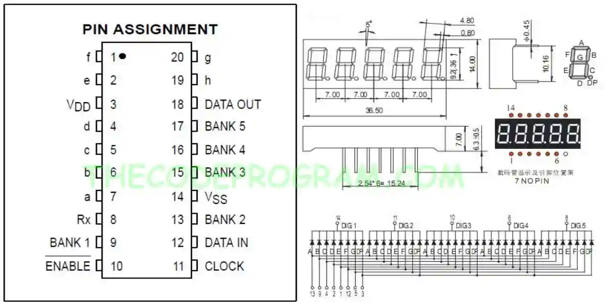
Firstly, What is MC14489
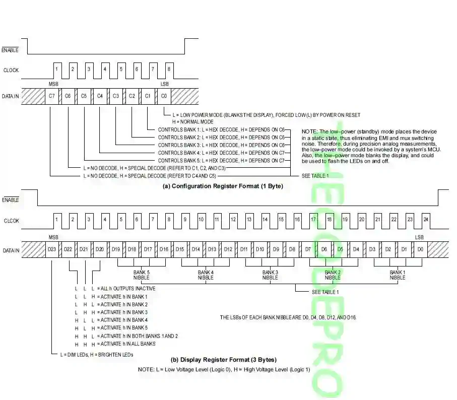
MC14489 is a LED driver which can be interfaced directly diodes. We can drive 7 segment displays or variations of this. LED's must be connected as common cathode logic. We can control maximum 5 digits with one MC14489 micro controller. MC14489 can be interfaced with SPI communication protocol. It accepts 24-bit data. We send all 24 digits numbers in 24bit . We can also send the configuration data with 8-bits.
Important Note : I always recommend to read the datasheet firstly.
Now let's start coding.
uint32_t delay_counter;
unsigned char digits[5];
Now we need to write our essential method. This method will send the data to MC14489 over Soft SPI method. Below code block will open/close the clock pin and during this operation it will set the data pin according to data bit.
void write_MC14489( uint8_t digitData) {

  int i=0;
  int pinState;

  GPIO_ResetBits(GPIOB, GPIO_Pin_13);
  GPIO_ResetBits(GPIOB, GPIO_Pin_15);

  for (i=7; i>=0; i--)  {
		GPIO_ResetBits(GPIOB, GPIO_Pin_13);
    if ( digitData & (1<<i) ) {
			GPIO_SetBits(GPIOB, GPIO_Pin_15);
    }
    else {
      GPIO_ResetBits(GPIOB, GPIO_Pin_15);
    }

    GPIO_SetBits(GPIOB, GPIO_Pin_13);
    GPIO_ResetBits(GPIOB, GPIO_Pin_15);
  }

  GPIO_ResetBits(GPIOB, GPIO_Pin_13);
}
void writeDigits(unsigned char digits[5])
{
	 GPIO_ResetBits(GPIOE, GPIO_Pin_7);

	 write_MC14489(  (0xff << 4) | digits[3]  ); // D23~D16
	 write_MC14489(  (digits[4] << 4) | digits[2]); // D15~D8
	 write_MC14489(  (digits[1] << 4) | digits[0] ); // D7~D0

	 GPIO_SetBits(GPIOE, GPIO_Pin_7);
}
void startDisplay()
{
   GPIO_ResetBits(GPIOE, GPIO_Pin_7);

   write_MC14489( 0x01);

   GPIO_SetBits(GPIOE, GPIO_Pin_7);
}
void startCounter(){

	for(int i=0; i<100000; i++){
		digits[0] = i % 100000 /10000;
   		digits[1] = i % 10000  /1000;
     		digits[2] = i % 1000   /100;
      		digits[3] = i % 100   / 10 ;
     		digits[4] = i % 10     ;

      		writeDigits(digits);

		delay_counter = 8000000;
		while(delay_counter--);
	}
}
int main()
{
	RCC_AHB1PeriphClockCmd(RCC_AHB1Periph_GPIOB, ENABLE);
	RCC_AHB1PeriphClockCmd(RCC_AHB1Periph_GPIOE, ENABLE);

	GPIO_InitTypeDef GPIO_Structure;

	GPIO_Structure.GPIO_Mode = GPIO_Mode_OUT;
	GPIO_Structure.GPIO_Pin = GPIO_Pin_13 | GPIO_Pin_15;
	GPIO_Structure.GPIO_OType = GPIO_OType_PP;
	GPIO_Structure.GPIO_Speed = GPIO_Speed_25MHz;
	GPIO_Init(GPIOB, &GPIO_Structure);

	GPIO_Structure.GPIO_Mode = GPIO_Mode_OUT;
	GPIO_Structure.GPIO_Pin =  GPIO_Pin_7 | GPIO_Pin_8;
	GPIO_Structure.GPIO_OType = GPIO_OType_PP;
	GPIO_Structure.GPIO_PuPd = GPIO_PuPd_UP;
	GPIO_Structure.GPIO_Speed = GPIO_Speed_25MHz;
	GPIO_Init(GPIOE, &GPIO_Structure);

	startDisplay();

	while(1)
	{
		 startCounter();

		 delay_counter = 65000;
		while(delay_counter--);
	}
}
Our program is ready now.
Example program is ready. You can see the working video on youtube: https://www.youtube.com/watch?v=VZ9MBTPulnI
That is all in this article.
You can reach the example code on Github via : https://github.com/thecodeprogram/TheSingleFiles/blob/master/STM32F4_MC14489_DisplayDriver.c
Burak Hamdi TUFAN