SPI Communication with Interrupt in Arduino
Let's get started.
First What is SPI?
SPI stands for Serial Periphal Interface. SPI lets the devices to communicate with each other to share information. In most application environmental devices use the SPI communication protocol to send the sensor value to device. SPI communication has one master device. This master device manage the everything.
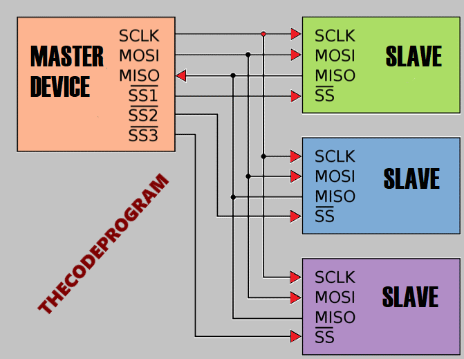
SPI has 3 lines. These are: MOSI, MISO and SCK. Sometimes we may need to communicate with multiple devices. In that case we will need external lines to set the active device. These lines call as CS (Chip Selection) or SS (Slave Selection). When we set the related devices SS pin as 0Volt we selected this related device. Below you will see the meanings of these lines:
- MOSI: Stands for Master Output Slave Input. This line lets the master device to send datas to the Slave device.
- MISO: Stands for Master Input Slave Output. This line lets the master device to receive datas from slave devices.
- SCK: This line oscilates the clock signal from the master device. This signal will synchronise the communication to make communication healthy.
Below image you can see the SPI Communication Schematic:
Now let's make an example with Arduino. In this example we are going to let the two arduinos to communicate with each other.
Below image you can see the pin connections of these two arduinos.
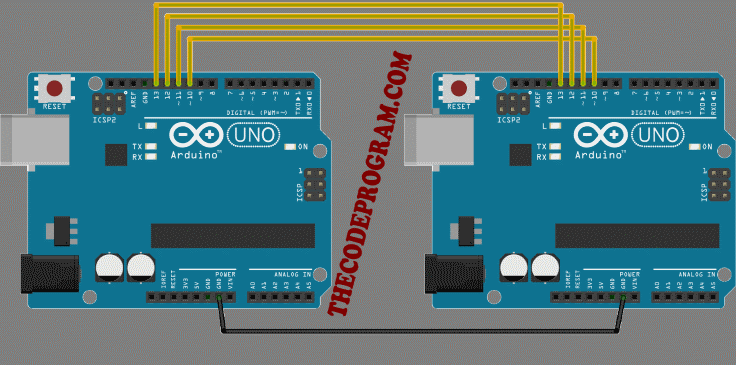
We selected the 11, 12 and13 as communication pins, and we set the 10. pin as Slave Selection pin. Also if you want to supply energy them seperatelly or you can connect them with 5V pins to supply both of them from connected arduino with USB to read serial datas.
Before The examples I want you to read the SPI hardware structs of the arduino.
SPCR Bit Values
| 7    | 6    | 5    | 4    | 3    | 2    | 1    | 0    |
| SPIE | SPE  | DORD | MSTR | CPOL | CPHA | SPR1 | SPR0 |

SPIE - Enables the SPI interrupt when 1
SPE - Enables the SPI when 1
DORD - Sends data least Significant Bit First when 1, most Significant Bit first when 0
MSTR - Sets the Arduino in master mode when 1, slave mode when 0
CPOL - Sets the data clock to be idle when high if set to 1, idle when low if set to 0
CPHA - Samples data on the falling edge of the data clock when 1, rising edge when 0
SPR1 and SPR0 - Sets the SPI speed, 00 is fastest (4MHz) 11 is slowest (250KHz)
First I will write the Master Device code.
MasterDevice.ino
//SPI Master Device
//We need to import SPI.h library first
#include <SPI.h>
//Our Slave Selection pin
#define SlaveSelection  10

int count = 0;

void setup()
{
  //Set SlaveSelection pin as output.
  pinMode(SlaveSelection, OUTPUT);
  //and Make it HIGH to prevent to start communication right away
  digitalWrite(SlaveSelection, HIGH);
  //Start the SPI communication.
  SPI.begin();
}

void loop()
{

    for(count=0; count<255; count++){
      sendSerialData(count , SlaveSelection);
      delay(2000);
    }
    delay(500);
}

void sendSerialData(char data, int SlaveSelection)
{
  //Enable slave arduino with setting the SlaveSelection pin to 0Volt
  digitalWrite(SlaveSelection, LOW);
  // Wait for a moment
  delay(10);
  //We sent the data here and wait for the response from device
  char receivedValue = SPI.transfer(data);
  //And then write the answer to the serial port
  Serial.println(receivedValue);
  //Disable slave arduino with setting the SlaveSelection pin to 5Volt
  digitalWrite(SlaveSelection, HIGH);
}
Below code block you will see the Slave Device Code:
SlaveDevice.ino
//Slave device of the SPI communication
#include <SPI.h>

char i = 0;

#define SlaveSelection  10

void setup()
{
  //Start the Serial Communication
  Serial.begin(9600);

  // initialize SPI :
  pinMode(SlaveSelection , INPUT); // Set SlaveSelection as input
  pinMode(13,OUTPUT);   // Set clk as output
  pinMode(11,OUTPUT);   // Set MOSI as output
  pinMode(12,INPUT);    // Set MISO as input

  // SPCR - SPI Control Register
  // According to struct table we enable the SPI and Interface
  SPCR  |= 0b11000000;
  // SPSR - SPI Status Register
  SPSR  |= 0x00;
}

void loop()
{
  delay(1000);
}

//SPI Interrupt function
ISR(SPI_STC_vect)
{
    //Here we read the SPI lines
    //This line will check data for every ASCII codes for 8-bit received data
    //SPDR -> SPI Data Read bit
    SPDR = i;
    i ++;
    if ( i > 255)
      i = 0;
    while(!(SPSR & (1 << SPIF)));
    //Load the received data to the variable
    char received = SPDR;
    //And send it to the serial communication bus
    Serial.println(received);
}
Now we are ready for the communication between two arduinos with the arduino.
You can reach the example application on github link https://github.com/thecodeprogram/Arduino_SPI_Example
That is all in this article.
Have a good SPI communication.
Burak Hamdi TUFAN