
How to use MC14489 with STM32F4 Std Periph and GPIO Pins
Hello everyone, in this article we are going to talk about usage of MC14489 with STM32F4 STD Periph Libraries and GPIO layers. We will use soft SPI protocol drive 5x7 Segment Display.Let's Get Started.
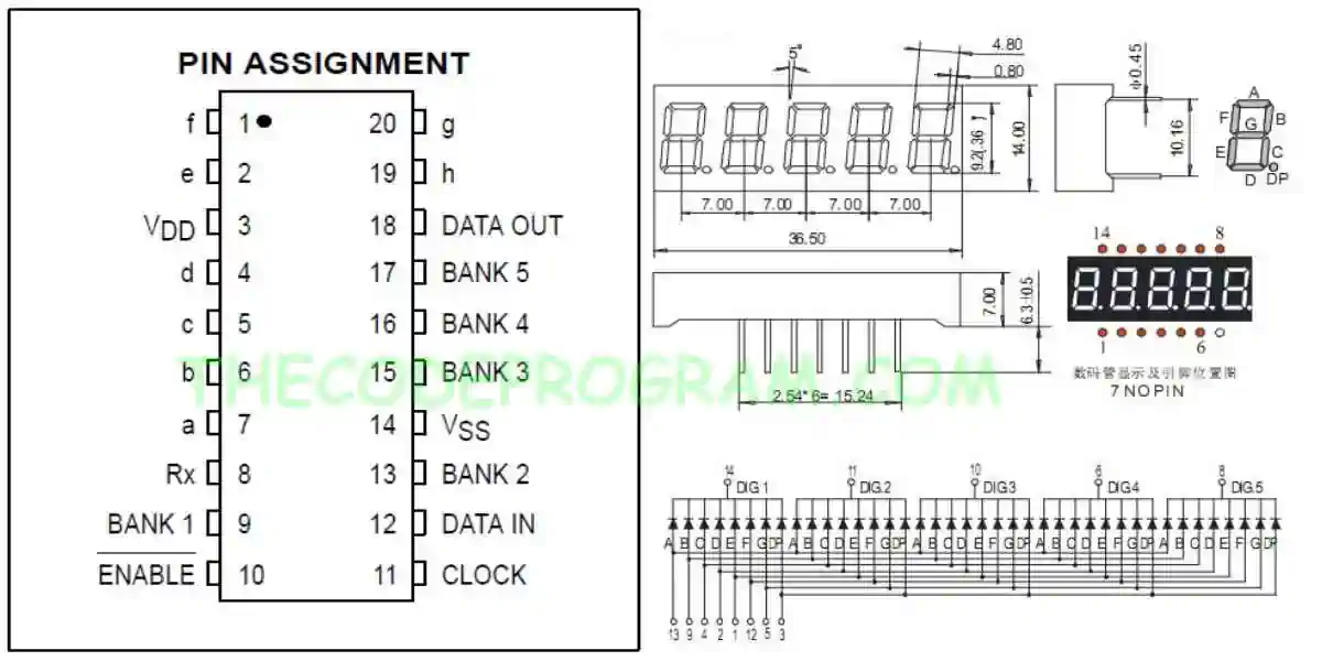
Firstly, What is MC14489
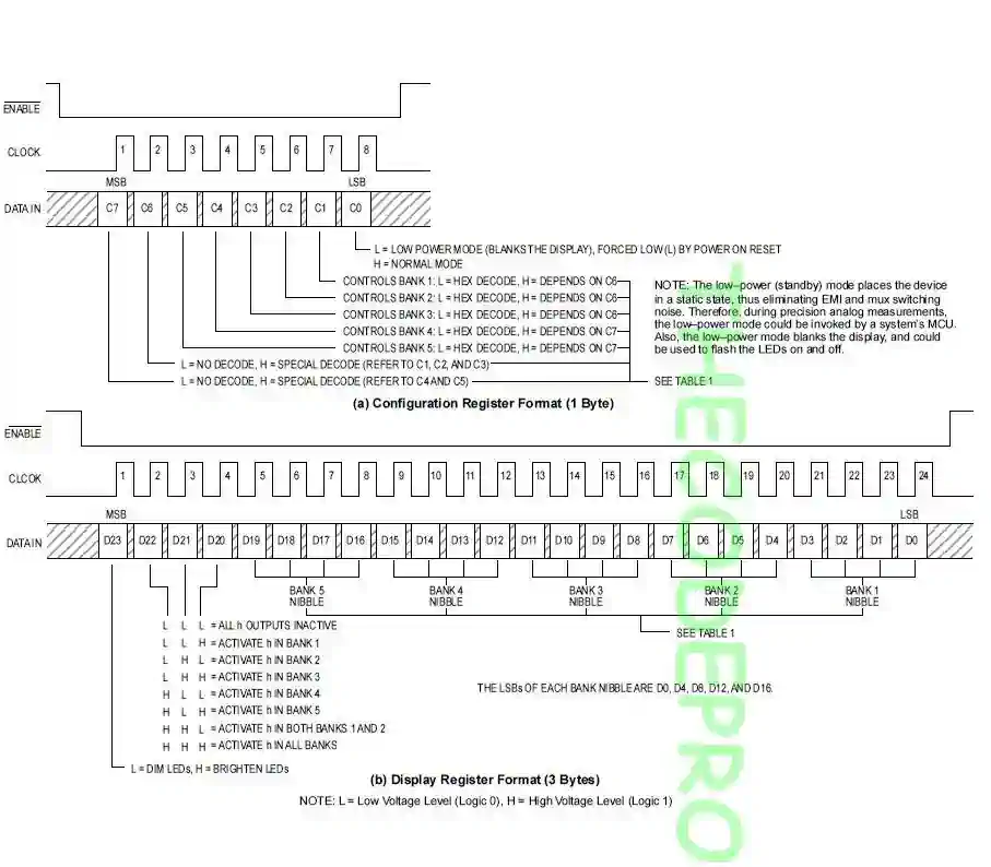
MC14489 is a LED driver which can be interfaced directly diodes. We can drive 7 segment displays or variations of this. LED's must be connected as common cathode logic. We can control maximum 5 digits with one MC14489 micro controller. MC14489 can be interfaced with SPI communication protocol. It accepts 24-bit data. We send all 24 digits numbers in 24bit . We can also send the configuration data with 8-bits.
Important Note : I always recommend to read the datasheet firstly.
Now let's start coding.
uint32_t delay_counter;
unsigned char digits[5];
Now we need to write our essential method. This method will send the data to MC14489 over Soft SPI method. Below code block will open/close the clock pin and during this operation it will set the data pin according to data bit.
void write_MC14489( uint8_t digitData) {

  int i=0;
  int pinState;

  GPIO_ResetBits(GPIOB, GPIO_Pin_13);
  GPIO_ResetBits(GPIOB, GPIO_Pin_15);

  for (i=7; i>=0; i--)  {
		GPIO_ResetBits(GPIOB, GPIO_Pin_13);
    if ( digitData & (1<<i) ) {
			GPIO_SetBits(GPIOB, GPIO_Pin_15);
    }
    else {
      GPIO_ResetBits(GPIOB, GPIO_Pin_15);
    }

    GPIO_SetBits(GPIOB, GPIO_Pin_13);
    GPIO_ResetBits(GPIOB, GPIO_Pin_15);
  }

  GPIO_ResetBits(GPIOB, GPIO_Pin_13);
}
void writeDigits(unsigned char digits[5])
{
	 GPIO_ResetBits(GPIOE, GPIO_Pin_7);

	 write_MC14489(  (0xff << 4) | digits[3]  ); // D23~D16
	 write_MC14489(  (digits[4] << 4) | digits[2]); // D15~D8
	 write_MC14489(  (digits[1] << 4) | digits[0] ); // D7~D0

	 GPIO_SetBits(GPIOE, GPIO_Pin_7);
}
void startDisplay()
{
   GPIO_ResetBits(GPIOE, GPIO_Pin_7);

   write_MC14489( 0x01);

   GPIO_SetBits(GPIOE, GPIO_Pin_7);
}
void startCounter(){

	for(int i=0; i<100000; i++){
		digits[0] = i % 100000 /10000;
   		digits[1] = i % 10000  /1000;
     		digits[2] = i % 1000   /100;
      		digits[3] = i % 100   / 10 ;
     		digits[4] = i % 10     ;

      		writeDigits(digits);

		delay_counter = 8000000;
		while(delay_counter--);
	}
}
int main()
{
	RCC_AHB1PeriphClockCmd(RCC_AHB1Periph_GPIOB, ENABLE);
	RCC_AHB1PeriphClockCmd(RCC_AHB1Periph_GPIOE, ENABLE);

	GPIO_InitTypeDef GPIO_Structure;

	GPIO_Structure.GPIO_Mode = GPIO_Mode_OUT;
	GPIO_Structure.GPIO_Pin = GPIO_Pin_13 | GPIO_Pin_15;
	GPIO_Structure.GPIO_OType = GPIO_OType_PP;
	GPIO_Structure.GPIO_Speed = GPIO_Speed_25MHz;
	GPIO_Init(GPIOB, &GPIO_Structure);

	GPIO_Structure.GPIO_Mode = GPIO_Mode_OUT;
	GPIO_Structure.GPIO_Pin =  GPIO_Pin_7 | GPIO_Pin_8;
	GPIO_Structure.GPIO_OType = GPIO_OType_PP;
	GPIO_Structure.GPIO_PuPd = GPIO_PuPd_UP;
	GPIO_Structure.GPIO_Speed = GPIO_Speed_25MHz;
	GPIO_Init(GPIOE, &GPIO_Structure);

	startDisplay();

	while(1)
	{
		 startCounter();

		 delay_counter = 65000;
		while(delay_counter--);
	}
}
Our program is ready now.
Example program is ready. You can see the working video on youtube: https://www.youtube.com/watch?v=VZ9MBTPulnI
That is all in this article.
You can reach the example code on Github via : https://github.com/thecodeprogram/TheSingleFiles/blob/master/STM32F4_MC14489_DisplayDriver.c
Burak Hamdi TUFAN
Tags
Share this Post
Author

I am a software developer experienced 15 years and here to share all my programming experiences. I have worked on so many platforms and programming languages especially C, C#, C++ and Java. I am studing PhD at Kocaeli University on Aviation Technologies. I am building softwares and technologies on aviation.

Comments