How to use MC14489 with Arduino Counter Example

Let's get started.
Firstly, What is MC14489
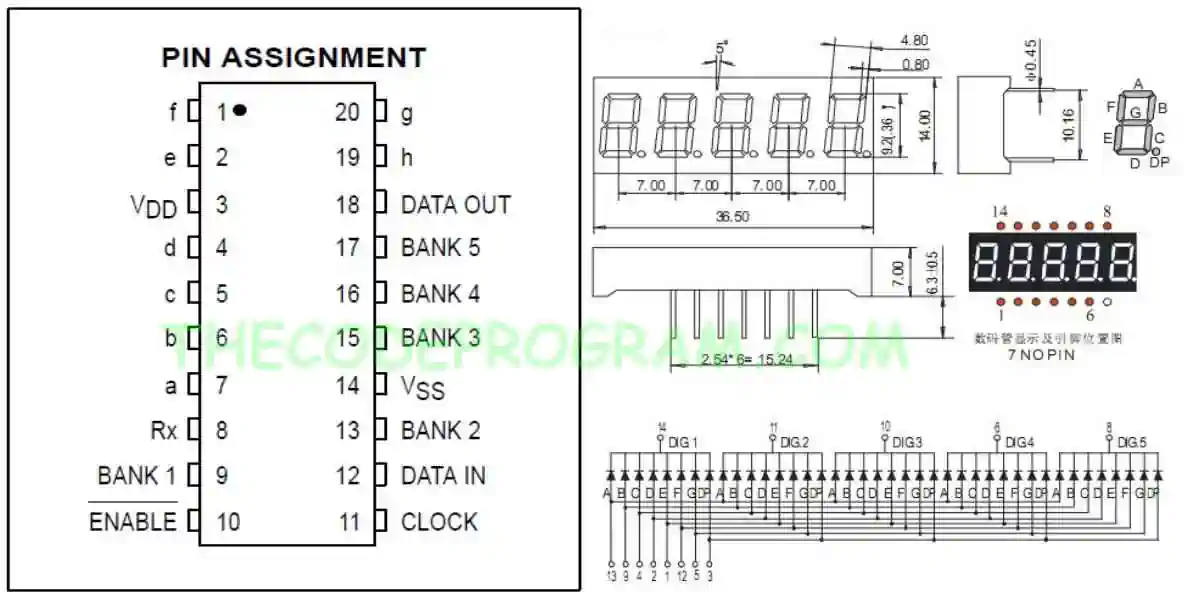
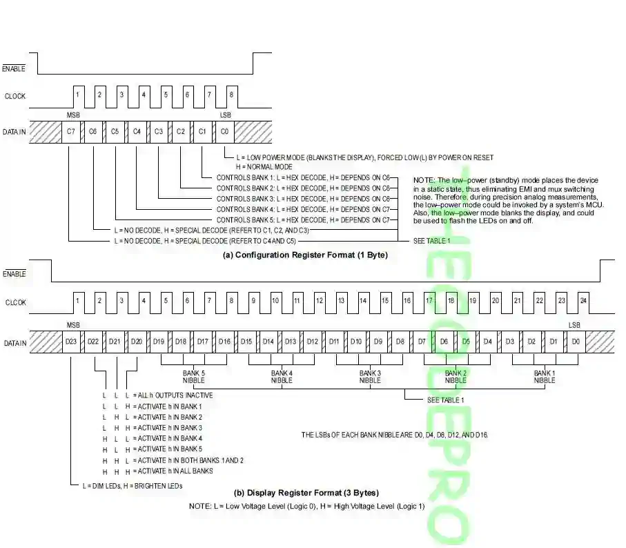
MC14489 is a LED driver which can be interfaced directly diodes. We can drive 7 segment displays or variations of this. LED's must be connected as common cathode logic. We can control maximum 5 digits with one MC14489 micro controller. MC14489 can be interfaced with SPI communication protocol. It accepts 24-bit data. We send all 24 digits numbers in 24bit . We can also send the configuration data with 8-bits.
Important Note : I always recommend to read the datasheet firstly.
In this example we are going to make a increasing counter one by one. Then we are going to show the current second on the display via MC14489.
Now let's start coding.
int data = 5;
int clk = 6;
int enable = 7;

byte digits[5];
Now our essential method to send data to MC14489 driver. This method will write the data bit by bit via software SPI communication to MC14489. We will call this method from other functions for sending data to MC14489.
void write_MC14489(byte digitData) {
  int i=0;
  int pinState;

  digitalWrite(data, 0);
  digitalWrite(clk, 0);

  for (i=7; i>=0; i--)  {
    digitalWrite(clk, 0);
    if ( digitData & (1<<i) ) {
      pinState= 1;
    }
    else {
      pinState= 0;
    }

    digitalWrite(data, pinState);
    digitalWrite(clk, 1);
    digitalWrite(data, 0);
  }

  digitalWrite(clk, 0);
}
And now we are going to parse the digits array to write values. We will send the datas as 8-bits. Because above write method is accepting 8 bit data. So I have sent all 24-bit value as three part. As you can see I have pulled down the enable pin then sent all 24-bit value and then pulled up back.
void writeDigits(byte digits[5]){
   digitalWrite(enable, LOW);
   write_MC14489(  (0xff << 4) | digits[3]  ); // D23~D16
   write_MC14489(  (digits[4] << 4) | digits[2]); // D15~D8
   write_MC14489(  (digits[1] << 4) | digits[0] ); // D7~D0
   digitalWrite(enable, HIGH);
}
void second_counter()
{
  for(int i=0; i<100000; i++){

      digits[0] = i % 100000 /10000;
      digits[1] = i % 10000  /1000;
      digits[2] = i % 1000   /100;
      digits[3] = i % 100   / 10 ;
      digits[4] = i % 10     ;

      writeDigits(digits);
      delay(1000);
  }

  delay(10);
}
void setup()
{
   pinMode(data, OUTPUT);
   pinMode(enable, OUTPUT);
   pinMode(clk, OUTPUT);

   //Start the MC14489
   digitalWrite(enable, LOW);
   write_MC14489( 0x01 );
   digitalWrite(enable, HIGH);
   delay(10);
}

void loop()
{
   second_counter();
}
Our program is ready now. You can reach the working video on youtube: https://www.youtube.com/watch?v=l605giHjw7Q
That is all in this article.
You can reach the example code on Github : https://github.com/thecodeprogram/Arduino_mc14489
Burak Hamdi TUFAN