SPI Communication with STM32 and ADS1118 using CubeMx
Hello everyone, In this article we are going to talk about SPI communication on STM32 and Cubemx. We are going to use HAL library in this article and make and example on communication on SPI.Now let's get started.
I will use STM32F042 and ADS1118 for communication. ADS1118 is an Analog to Digital converter. We will fetch the values of all connected potentiometer values to our STM32F042 via ADS1118.
I HIGHLY RECOMMEND TO READ ADS1118 DATASHEET FIRST.
You can reach the datasheet via here.

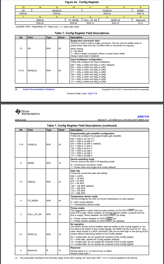
Now according to above picture we will create a register struct to manage ADS1118. We will send the parameters and set some configurations like speed, which adc port to read.
typedef union
{
    struct
    {
        volatile unsigned char    RESV  			:1;   //it does not matter 0 or 1
        volatile unsigned char    NOP         :2;
        volatile unsigned char    PULLUP      :1;
        volatile unsigned char    TS_MODE     :1;
        volatile unsigned char    DR          :3;
        volatile unsigned char    MODE        :1;
        volatile unsigned char    PGA         :3;
        volatile unsigned char    MUX         :3;
        volatile unsigned char    OS          :1;   //high
    } stru;
    volatile unsigned int  word;
    volatile unsigned char byte[2];
} ADS_InitTypeDef;


//ADS1118 Configuration Registers
ADS_InitTypeDef adsConfigReg;
Later now we need to configurate our ADS1118, to do this we have send variables to microchips' built-in registers with above structure. Below code block will do it.
	//ADS Structure variable
	ADS_InitTypeDef ConfigReg;

	//We will use it as single-shot mode
	adsConfigReg.stru.OS				=	0x1;   //high
	// 0x4 enables AIN0 , 0x5 enables AIN1,0x6 enables AIN2 and 0x7 enables AIN3 .
	adsConfigReg.stru.MUX			=	0x4;
	//Programmable Gain amplifier
	adsConfigReg.stru.PGA      = 0x1;		//  FSR 4.096V
	//Continuous mode or single-shot mode
	adsConfigReg.stru.MODE			=	0x1;
	//Data Rate register
	adsConfigReg.stru.DR       = 0x4;
	//If you want to use this chip as a temperature sensor set this as 1.
	adsConfigReg.stru.TS_MODE	=	0x0;
	//Enable built-in pull-up resistors.
	adsConfigReg.stru.PULLUP		= 0x1;
	//Command mode. Set this always as 0x01.
	adsConfigReg.stru.NOP			=	0x1;
	//Reserved register. It does not matter this register is 1 or 0.
	adsConfigReg.stru.RESV			= 0x1;

	Assign the values into one word belong to global variable defined above.
	adsConfigReg.word=ConfigReg->word;

	HAL_Delay(100);
I want to say something about MUX register: With this register we will set the built-in multiplexer inside the ADS1118. This multiplexer allows whic adc will be sent to the master. Also we can read differance of Analog inputs. You can get the much more information from the datasheet of ADS1118.
Now we are ready to send the parameters and get the value of selected analog input.
//Below function will send the data to the chip and fetch the result data
HAL_SPI_TransmitReceive(&hspi1,(uint8_t*)(adsConfigReg.byte), (uint8_t*) aRxBuffer, 2, 100);
//Wait a little bit
HAL_Delay(100);
//and load the data into variable.
int deger = aRxBuffer[0] | aRxBuffer[1] << 8;
//you can make the conversations for your own usage.
float voltage_brake =  deger * 0.250;
Now we are ready to use the ADS1118.
Have a good Analog to Digital Converting :D
Burak Hamdi TUFAN
Tags
Share this Post
Author

I am a software developer experienced 15 years and here to share all my programming experiences. I have worked on so many platforms and programming languages especially C, C#, C++ and Java. I am studing PhD at Kocaeli University on Aviation Technologies. I am building softwares and technologies on aviation.


Comments
Hello, very interesting article. I used an arduino to read ads1118, Now, I would like to do it with a st nucleo. I copied and pasted your code, but it doesn't work. Unfortunately, I can't get the data. could you help me? Thank you
2021/03/04 12:26:02Hello Joan, You need to read and apply all of procedure to get it work, Because in article I am making some configurations on SPI to work good. Only copying the whole code will not work. Thank you.
2021/03/06 16:18:16Very useful article ! I have some questions: 1- how did we get the coefficient 0.250? 2-could you please explain what happens here? int deger = aRxBuffer[0] | aRxBuffer[1] << 8; 3-could you please explain which data stays in adsConfigReg.byte before we send it through HAL_SPI_TransmitReceive ?
2021/06/15 23:09:35Thank you very much for your questions
2021/06/28 08:10:551- That coefficient value is just a value that setted. It depends on your configuration. In here it is just a number to scale the value.
2-We are receiving data with two 8-bit variables via HAL_SPI_TransmitReceive function. We are binding both variable to deger variable. deger = [8-bit][8-bit]. First 8-bit aRxBuffer[1] because it has been shifted to left.
3-In debug screen we can see all ads configuration datas in byte area. Because these values inside union are using same address on memory. So the order of config variables is important. If you change the definition order you will change the configurations. byte variable delegates all data in the struct. You should see the usage of UNION keyword.
Hello! once again. Previous time I said that your code didn't work with me. Have you given a look? I count on you in this driver ... I have been struggled with it one month, I can't read data from ads1118. If you see my message or have an idea please don't hesitate to contact me.
2021/07/11 23:33:13Hello, I also had some trouble on ads1118 over SPI, I have used ads1115 with I2C and there is no problem, everything was great with ads1115. I strongly recommend to use ads1115.
2021/07/13 17:38:34Hello, Mr. Burak. After a couple of months trying hardly I finally got it working. If you are insterested I can share the code with you. I did it with HAL.
2021/09/10 01:13:44Hello Benedito, I am really glad for this. If you allow I would love to share it here with you name.
2021/09/10 20:09:01Hey I'm using the ads8681 ADC but I'm not able to config it can u suggest me and please share ur code also so I can refer
2022/02/25 12:44:49Hello, These configurations for ads1118, first you need to read ads8681 datasheet. Detailed communication data should be placed in datasheet of related chip. Maybe communication protocol is completely different, so sharing the entire source probably will not help you. You should foccus on communication.
2022/02/27 16:19:08