H-Bridge Circuit and Control a DC-Motor
Hello everyone, In this article we are going to talk about H-Bridge circuit. How can we build this circuit and what can we do with H-Bridge circuit and implementation on a DC motor control circuit.Let's get started.
When we need to drive a DC motor we just need to supply electricty to its inputs. But What if we need to rotate the DC Motor both directions? To do this we should change the inputs and suply the voltage again. In normal operation this generally not possible. So we need a electronic circuit to accomodate this action instead of us. This electronic circuit named as H-Bridge.
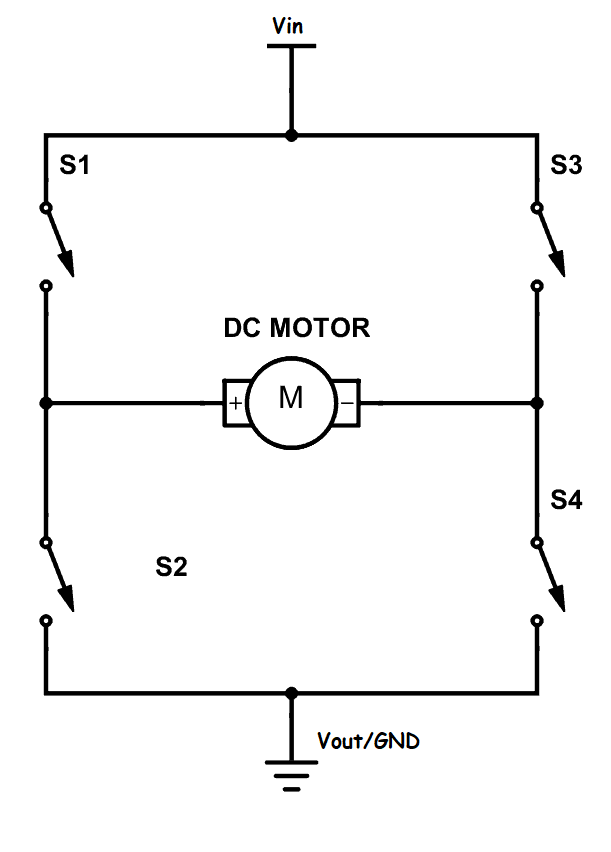
A H-Bridge circuit consist of voltage input, voltage output and four switches. We will supply the electricity with voltage in and out, then we will make some combinations with these switches to change the voltage path and motors rotation direction. Attention! Wi will not change the connection, just open and close some switches. This makes the easier to control a DC motor rotation.
There are some important things which we have to be carefull about H-Bridge circuits. These are:
- We have to select switching component that can work with enough current values. If we use the transistor that can work with maximum 2 amperes, it will be damaged over this value.
- We should use PNP type transistors at the upper side of circuit and NPN type transistors at the bottom side of circuit.
- We should be careful to short circuit. If we close the switches directly from positive to negative, we weill probably burn our circuit and electronic components.
- We should consider the discharging times of component. I mean If the timing and sensitivity is important for us we can use transistor not to magnetic relays. Of course we can use magnetic relays when we need much amperes but not need the sensitivity.
- We alwasy consider the voltage drops of the transistor or relay which we connected as switching components.
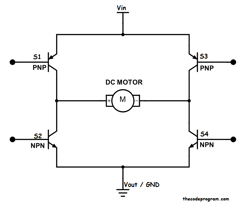
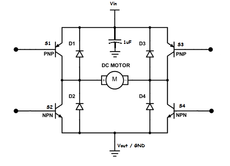
Locating of the transistors is important.
As you can see the above image PNP transistors located at the upper side of circuit and NPN transistors located bottom side of circuit.
So, Why to do this?
Firstly Never forget to consider this:
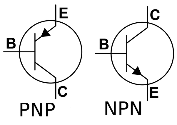
The arrow mark at the transistor symbol is always show the emitter side.
At the PNP transistor the current goes from Emitter to Collector. So you should connect the load to output of the transistor.
At the NPN transistor the current goes from Collector to Emitter. So you should connect the load to input of the transistor.
Most microcontrollers have 3.3V digital output voltage. Also you will need more voltage than 3.3v which supplied from microcontroller digital output. You can supply more voltage with PNP type transistor. For example if your motor need 12-VDC You can connect a +9V to the emitter pin of PNP transistor and microcontroller digital output which has 3.3V to the base pin of PNP transistor. At the end you will have 12.3V DC voltage at the collector pin. You can measure this value with a standart multimeter or you can connect here a DC-Motor.
If we connect the NPN transistr to the positive voltage output with the same directions the motor will not be working. Because we habeen connected the load output of the NPN transistor instead of input.
As our tansistor and connection subject okay, now we can talk about switching for rotation directions.
As I mentioned above we are changing the path of the voltage and so motor rotation direction is changing.
Below images you can see the current flow directions.
When we close the Switch 1 and Swtch 4, open the Switch 2 and switch 3 The current flow direction will be like below image:
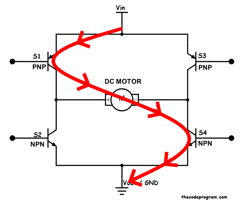
When we close the Switch 2 and Swtch 3, open the Switch 1 and switch 4 The current flow direction will be like below image:

As a result of these combinations voltage inputs will be changed and the direction of the motor will be changed.
At last we are ready to rotate our motor with both directions. But do we know if some voltages remaining in the circuit after opening the switches it will go somewhere else. To avoid this we have connected the returning path with diodes to the Ground. By this way the remaining voltage will go to the GND safely. And it will protect the circuit.
NOTE: You can change the motor speed with the PWM signal. This article just about H-Bridge and DC-Motor controlling.
That is all in this article.
Have a nice DC Motor controlling.
Burak Hamdi TUFAN.
Tags
Share this Post
Author

I am a software developer experienced 15 years and here to share all my programming experiences. I have worked on so many platforms and programming languages especially C, C#, C++ and Java. I am studing PhD at Kocaeli University on Aviation Technologies. I am building softwares and technologies on aviation.


Comments
Can I use only 2 switches (from arduino analog pins ) by connecting the base if S1 to collector on S4 with a resistor, and vice versa, base from S3 to collector S2. Then I would only need 2 analog pwm's for either direction.
2022/04/20 11:43:12Hello, Purpose of using 4 switches is rotate the motor to both directions. If you remove the switches at S1 and S4 and keep connected S2 and S3 it will rotate single direction. If you send a modulated voltage it will set the speed of rotation. On arduino you can connect the S3 and S4 to ground and and connect S1 and S2 to PWM outputs. So you can control with only two pins.
2022/04/21 21:49:31