Shift Operator example with ODR in STM32F4 StdPeriph
Hello everyone, in this article we are going to talk about shift operators in STM32F4 and StdPeriph with C language. We are going to use ODR register of STM32F429ZI Nucleo board and make a floating LED application.Let's get started.
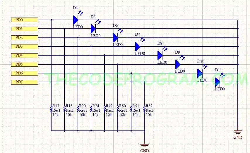
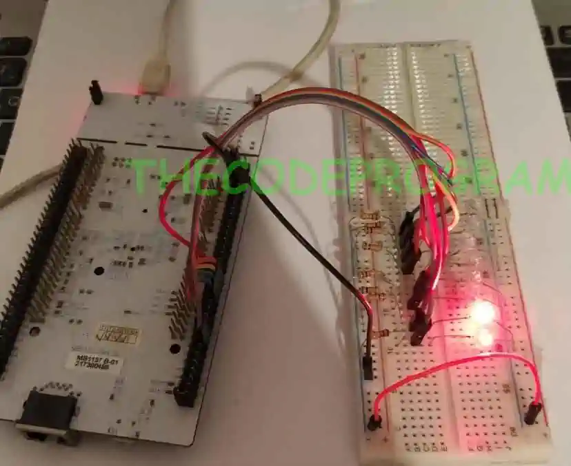
As you can see above schematic I have made the connections. Now I will write some codes to perform.
First I need to activate required GPIOD periphal bus and I need to activate required pins.
Below code block will activate the required GPIO bus. I will enable the GPIO bus here.
RCC_AHB1PeriphClockCmd(RCC_AHB1Periph_GPIOD, ENABLE);
GPIO_InitTypeDef GPIO_InitStructure;
GPIO_InitStructure.GPIO_Mode    = GPIO_Mode_OUT;
GPIO_InitStructure.GPIO_Pin     = GPIO_Pin_0 | GPIO_Pin_1 | GPIO_Pin_2 | GPIO_Pin_3 | GPIO_Pin_4 | GPIO_Pin_5 | GPIO_Pin_6 | GPIO_Pin_7;
GPIO_InitStructure.GPIO_OType   = GPIO_OType_PP;
GPIO_InitStructure.GPIO_Speed   = GPIO_Speed_100MHz;
GPIO_Init(GPIOD, &GPIO_InitStructure);
Until here our configurations are ready. We are going to perform the register data shifting in here.
void delay(uint32_t sure)
{
	uint32_t counter;
	for(int i=0; i < sure; i++){
		counter++;
	}
}
I strongly recommend to take a look at https://thecodeprogram.com/access-gpio-pin-states-with-odr-and-idr-in-stm32-stdperiph if you do not have any ideo ODR and IDR registers of STM32 GPIO.
	while(1)
	{
		GPIOD->ODR = 0x01; // 0b0000 0001

		for(uint16_t i = 0;i < 8; i++)
		{
			GPIOD->ODR = GPIOD->ODR << 1;
			delay(1000000);
		}

		for(uint16_t i=8; i>0; i--)
		{
			GPIOD->ODR = GPIOD->ODR >> 1;
			delay(1000000);
		}

		delay(1000000);
	}
You can also reach the working video on youtube: https://www.youtube.com/watch?v=rtIlhj3eMbo
That is all in this article.
Have a great shifting data.
Burak Hamdi TUFAN
Tags
Share this Post
Author

I am a software developer experienced 15 years and here to share all my programming experiences. I have worked on so many platforms and programming languages especially C, C#, C++ and Java. I am studing PhD at Kocaeli University on Aviation Technologies. I am building softwares and technologies on aviation.


Comments