Access GPIO pin states with ODR and IDR in STM32 StdPeriph
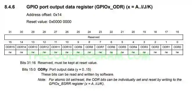
Hello everyone in this article we are going to talk about Output Data Register in STM32F4. Arm itself called this register as ODR. We will access the ODR of the related GPIO port pin states.Now let's begin.
Firstly I want to talk about what ODR and IDR
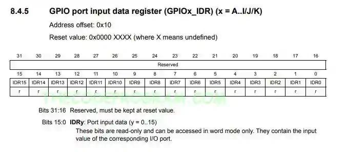
IDR is one of the GPIO registers which holds the input states of pins of a GPIO port. We can read the entire pin status of a GPIO portwith IDR register.
In this article we are going to make examples with STM32F429ZI-NUCLEO board.
I will use the blue user button and red, Blue, Green leds to access these registers.
As you can see the last 16-bits of the both registers what we are in need. Now we are going to make examples to read and write these registers.
	GPIO_InitTypeDef GPIO_StructureLed;
	GPIO_InitTypeDef GPIO_StructureButton;

	RCC_AHB1PeriphClockCmd(RCC_AHB1Periph_GPIOB, ENABLE);
	RCC_AHB1PeriphClockCmd(RCC_AHB1Periph_GPIOC, ENABLE);

	GPIO_StructureLed.GPIO_Mode = GPIO_Mode_OUT;
	GPIO_StructureLed.GPIO_Pin = GPIO_Pin_0 | GPIO_Pin_7 | GPIO_Pin_14 ;
	GPIO_StructureLed.GPIO_OType = GPIO_OType_PP;
	GPIO_StructureLed.GPIO_Speed = GPIO_Speed_100MHz;
	GPIO_Init(GPIOB, &GPIO_StructureLed);

	GPIO_StructureButton.GPIO_Mode = GPIO_Mode_IN;
	GPIO_StructureButton.GPIO_Pin = GPIO_Pin_13;
	GPIO_StructureButton.GPIO_OType = GPIO_OType_PP;
	GPIO_StructureButton.GPIO_PuPd = GPIO_PuPd_DOWN;
	GPIO_StructureButton.GPIO_Speed = GPIO_Speed_100MHz;
	GPIO_Init(GPIOC, &GPIO_StructureButton);
	while(1)
	{
		if(GPIO_ReadInputDataBit(GPIOC, GPIO_Pin_13))
			GPIO_SetBits(GPIOB,GPIO_Pin_0 | GPIO_Pin_7 | GPIO_Pin_14 );
		else
			GPIO_ResetBits(GPIOB,GPIO_Pin_0 | GPIO_Pin_7 | GPIO_Pin_14);
	}

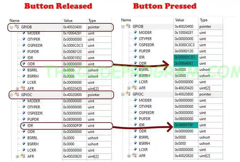
0x4081 = 0b0100000010000001
As you can see above binary value 0. 7. and 14. bits are HIGH. This means related pins of the GPIOB port are HIGH.
0xDF4F = 0b 1101 1111 0100 1111
0xFF4F = 0b 1111 1111 0100 1111
As you can see bit 13 changed from LOW to HIGH. This means this pin activated via button pressing.
We can also check the required pin is HIGH or LOW with bitwise operators in C. All we need to use masking the IDR value. We Are going to mask with a value which required bits are HIG and the remain is low.
#include <stdbool.h> //We need this header for bool variable
bool checkMaskForIDR(uint16_t IDR_Value, uint16_t mask_input){
	return IDR_Value & mask_input;
}
We can also change the pin output status with directly ODR value. But in here we have to be carefull about do not disturbing the other bits. Because other pins may be in use for another purpuse. So we need to use masking. But if the other pins are not important we can change them too.
	if(GPIO_ReadInputDataBit(GPIOC, GPIO_Pin_13))
		GPIOB->ODR = 0x00004081;
	else
		GPIOB->ODR = 0x00000000;
If you want to change only required pins we can use the OR bitwise operator. We will mask the required value with OR 0 and other values will not be affected.
	if(GPIO_ReadInputDataBit(GPIOC, GPIO_Pin_13))
		GPIOB->ODR |= 0x00004081;
	else
		GPIOB->ODR |= 0x00000000;
You can check the Explanation of Operators in C article to get detailed information of operators in C.
That is all in this article.
Have a good accessing GPIO registers.
Burak Hamdi TUFAN.


Comments