Stm32F4 StdPeriph with MAX7219 5x7 Segment Display
Hello everyone, in this article we are going to talk about driving MAX7219 with STM32F4 and StdPeriph Libraries. We will drive a 5 Digits 7 Segment Common Cathode Display.Let's Begin.
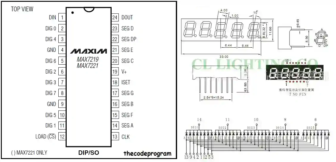
Firstly What is MAX7219
MAX7219 is a common cathode 7 segment display driver. You can also drive the 8x8 dot matrix displays with MAX7219. It communicates with other microcontrollers using SPI transfer protocol. All configurations can be setted on SPI via values on preconfigured registers.
IMPORTANT : I always strongly suggest to read datasheets of all external chips.
Also It is important to add specified resistor on datasheet, also add a pull-up resistor between 5v and Chip Select pin. Also adding a 10uF capacitor between MAX7219 GND and microcontroller GND may be good for filtering. This will filter the unwanted staying low at every changes.
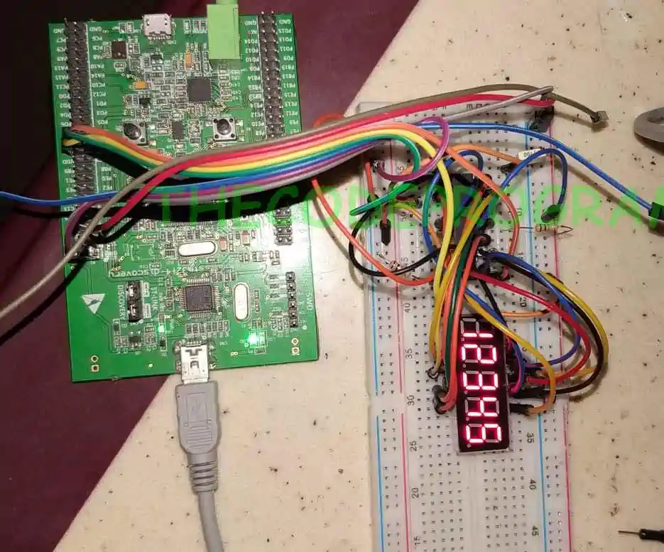
In here we are going to use STM32F4 discovery board and StdPeriph libaries. We will use only GPIO here. This method known as Software SPI communication. We will send the datas through making the data pin LOW and HIGH with specified clock pin
#define DECODE_REGISTER        0x09
#define INTENSITY_REGISTER     0x0A
#define SCAN_LIMIT_REGISTER    0x0B
#define SHUTDOWN_REGISTER      0x0C
#define DISPLAY_TEST_REGISTER  0x0F

#define DIGIT_1_REGISTER       0X01
#define DIGIT_2_REGISTER       0X02
#define DIGIT_3_REGISTER       0X03
#define DIGIT_4_REGISTER       0X05
#define DIGIT_5_REGISTER       0X04

#define DELAY_TIME 1
void the_delay(int i)
{
	while(i) i--;
}
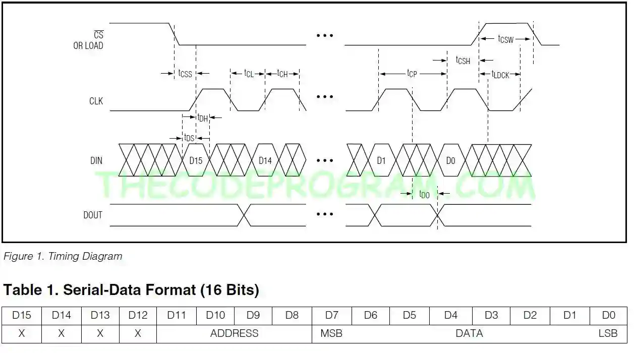
Now Firstly we are going to write essential function. This function will send the data to related register via software SPI communication. This putByte method will produce a Clock signal and data signal for every clock clock signal. We are going to send 8 bit data so our essential variable is equal to 8 here. We will mask this data and to send it byte by byte.
void MAX7219_PutByte(uint8_t data)
{
  uint8_t i = 8;
  uint8_t mask;
  while(i > 0) {
    mask = 0x01 << (i - 1);
	GPIO_ResetBits(GPIOB, GPIO_Pin_6);
    if (data & mask){
	GPIO_SetBits(GPIOB, GPIO_Pin_5);
    }else{
	GPIO_ResetBits(GPIOB, GPIO_Pin_5);
    }
     GPIO_SetBits(GPIOB, GPIO_Pin_6);
    --i;
  }
}
void MAX7219_SendData(char reg, char data)
{
  GPIO_ResetBits(GPIOB, GPIO_Pin_7);
  MAX7219_PutByte(reg);
  MAX7219_PutByte(data);
  GPIO_SetBits(GPIOB, GPIO_Pin_7);
  GPIO_SetBits(GPIOB, GPIO_Pin_7);

	the_delay(DELAY_TIME);
}
Until here our required functions are ready. Now we are going to use these functions via main function.
int main()
{
	//Firstly activate the periph bus
	RCC_AHB1PeriphClockCmd(RCC_AHB1Periph_GPIOB, ENABLE);

	//and activate the required pins
	GPIO_InitTypeDef GPIO_InitStructure;

	GPIO_InitStructure.GPIO_Mode  = GPIO_Mode_OUT;
	GPIO_InitStructure.GPIO_OType = GPIO_OType_PP;
	GPIO_InitStructure.GPIO_Speed = GPIO_Speed_25MHz;
	GPIO_InitStructure.GPIO_PuPd  = GPIO_PuPd_UP;
	GPIO_InitStructure.GPIO_Pin 	= GPIO_Pin_5 | GPIO_Pin_6 | GPIO_Pin_7;
	GPIO_Init(GPIOB, &GPIO_InitStructure);

	//then we are going to prepare the MAX7219 chip
	MAX7219_SendData(SHUTDOWN_REGISTER, 1);
	MAX7219_SendData(SCAN_LIMIT_REGISTER, 0x04);
	MAX7219_SendData(DECODE_REGISTER, 0xff);
	MAX7219_SendData(INTENSITY_REGISTER, 0xff);

	//and write the characters on display.
	MAX7219_SendData(DIGIT_1_REGISTER, 1);
	MAX7219_SendData(DIGIT_2_REGISTER, 2);
	MAX7219_SendData(DIGIT_3_REGISTER, 3);
	MAX7219_SendData(DIGIT_4_REGISTER, 4);
	MAX7219_SendData(DIGIT_5_REGISTER, 5);

	while(1)
	{

	}
}
That is all in this article.
You can reach the code file on Github via : https://github.com/thecodeprogram/TheSingleFiles/blob/master/Stm32F4_StdPeriph_MAX7219_5x7_Segment_Display.c
Burak Hamdi TUFAN.
Tags
Share this Post
Author

I am a software developer experienced 15 years and here to share all my programming experiences. I have worked on so many platforms and programming languages especially C, C#, C++ and Java. I am studing PhD at Kocaeli University on Aviation Technologies. I am building softwares and technologies on aviation.


Comments