How to use GPIO Interrupts in STM32F4 CubeMX
Hello everyone, in this article we are going to see how to manage GPIO Interrupts in STM32 with CubeMX and Keil. I will use STM32F0 discovery board to create an example and run the program.Let's begin.
STM32F429 has 16 GPIO Interrupt line. This means you can use Px0 - Px15 pins for interrupt. In here PA0 and PB0 also PC0 are on the same interrupt lines. In tis exaple the board has a USER BUTTON on PC13 pin. When the user activated this related pin the interrupt will be activated.
First we create a project and select the board as STM32F0-Discovery board based on STM32F051 like below image.
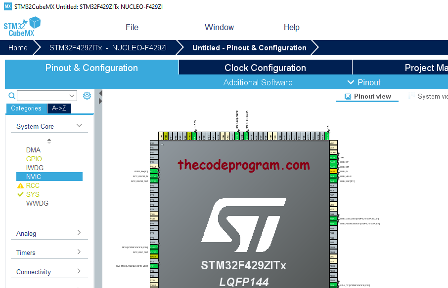
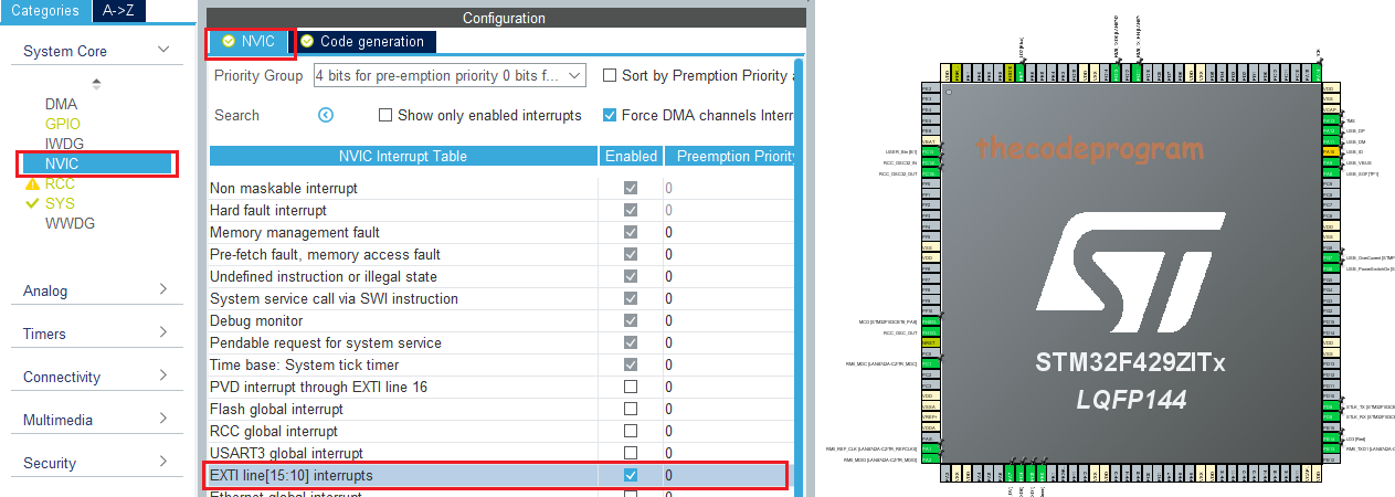
After creating the project, we have to enable the required GPIO interrupts. In STM32 we have to enable the EXTI interrputs to use.
STM32F4 has seven GPIO interrupt lines. Below table you can see the these interrupt lines:
| IRQ Name | IRQ Handler | Connected Pins |
|---|---|---|
| EXTI0_IRQn | EXTI0_IRQHandler | Connected to pin 0 |
| EXTI1_IRQn | EXTI1_IRQHandler | Connected to pin 1 |
| EXTI2_IRQn | EXTI2_IRQHandler | Connected to pin 2 |
| EXTI3_IRQn | EXTI3_IRQHandler | Connected to pin 3 |
| EXTI4_IRQn | EXTI4_IRQHandler | Connected to pin 4 |
| EXTI9_5_IRQn | EXTI9_5_IRQHandler | Connected to pins 5 to 9 |
| EXTI15_10_IRQn | EXTI15_10_IRQHandler | Connected to pins 10 to 15 |
At the STM32F429 has the handlers in it. Below image you can see the IRQ handlers and EXTI GPIO handlers as marked with red square. We are going to need that IRQ handlers.
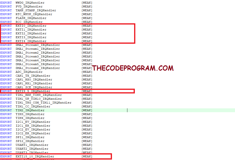
In this case we are going to use EXTI15_10_IRQHandler handler. Because our USER Button pin connected to PC13 pin.
After this Generate the code and create the Keil MDK project.
Since now, we have to write our interrupt callback function with the required GPIO_Pin parameter. With this paramete, when the GPIO pin activated this function will run. If we do not specified the pin it will be activated and the do same things for all pins. So we need to specify the pins for the related tasks in this method.
Make sure Below code block is located in the project and if not exist you must locate it:
/* USER CODE BEGIN 4 */

void HAL_GPIO_EXTI_Callback( uint16_t GPIO_Pin)
{
	if(GPIO_Pin == USER_Btn_Pin){
	   //This block will be triggered after pin activated.
	}
}

/* USER CODE END 4 */
Now our project is ready and we are going to write below code block to use the GPIO interrupts and we are going to activate a LED on the board which is named as LD1.
Below code block you will see it.
/* USER CODE BEGIN 4 */

void HAL_GPIO_EXTI_Callback( uint16_t GPIO_Pin)
{
	if(GPIO_Pin == USER_Btn_Pin){
	   //This block will be triggered after pin activated.
		HAL_GPIO_WritePin(LD1_GPIO_Port, LD1_Pin, GPIO_PIN_SET);
		HAL_Delay(10);
		HAL_GPIO_WritePin(LD1_GPIO_Port, LD1_Pin, GPIO_PIN_RESET);
	}
	else{
		//Do not do anything when else.
		__NOP();
	}
}

/* USER CODE END 4 */
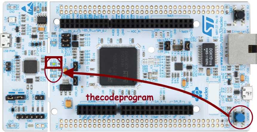
Below image you can see the output of the prject. As you can see when you press the blue User Button it will activate the LD1 LED with interrupt.
That is all in this article.
Have good interrupting the GPIO pins
I wish you all have healthy days.
Burak Hamdi TUFAN
Tags
Share this Post
Author

I am a software developer experienced 15 years and here to share all my programming experiences. I have worked on so many platforms and programming languages especially C, C#, C++ and Java. I am studing PhD at Kocaeli University on Aviation Technologies. I am building softwares and technologies on aviation.


Comments