Differences between I2C and SPI
Hello everyone, in this article we are going to talk about differences between I2C and SPI communication protocols which are using in embedded systems widely. Firstly I have to explain what is SPI and what is I2C.What is SPI ?
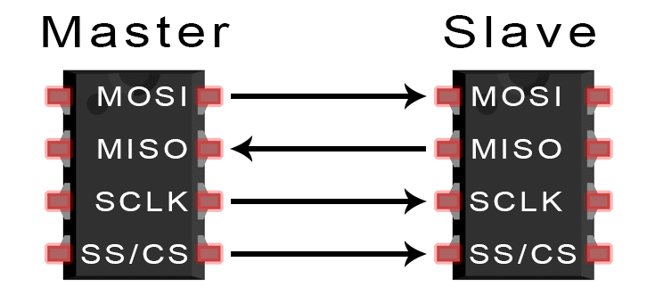
SPI stands for Serial Peripheral Interface. SPI is a serial data transfer protocol is generally using to transfer data between microprocessors and sensors, shift registers etc.. devices. SPI protocol has seperated clock and data buses(MOSI and MOSI). On the clock line there is a signal which is carrying an HIGH-LOW signal continuously to keep data syncronised. Common serial bus has no clock bus so transferer and receiver working individual. Tranfer device just send the data in a specified frequency and the receiver device fetch the data specified frequency. If one of them miss the frequency, the data will be disturbed and probably break down. In SPI protocol master device creates a logic signal with data signal to specify the transmission frequency. In this way data won't be broke down even if the minor changes happened at the devices frequencies.
What is I2C ?
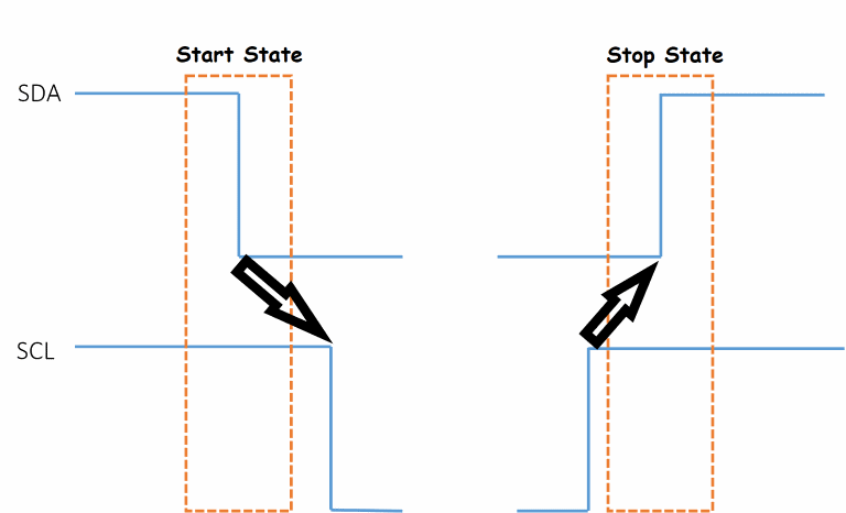
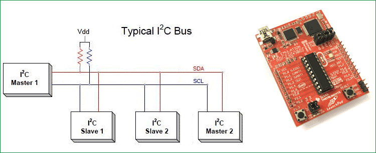
I2C stands for Inter-Integrated Circuit. I2C protocol is a serial communication with two cables. These cables are SDA (Serial DATA) and SCL (Serial Clock). I2C discovered by Philips. I2C can work with low frequency. Microcontroller need to be connected with pull-up resistors the Vdd to SDA and SCL pins. When I2C discovered at first time default communicaton frequency was 100kHz. After that developed Fast mode and maximum frequency increased 400kHz. Nowadays High-Speed and Ultra-Speed modes developed at 3.4 MHZ and 5MHz. Every I2C device must have an adress. These adresses must have 8 bits. / bits of adress is the unique adress and last bit is specify the transmission direction. Communication starts with a HIGH-to-LOW state on SDA line before SCL lines' HIGH-to-LOW state and first data packet must be adress and then other datas. Ending message packet is a LOW-to-HIGH state after SCL line is HIGH.
Now we have basic information about what I2C and SPI are. Now we can compare them and we can decide which one we have to use in our project.
Distance Issue
If your board is a single piece board and speed is important for you of course you should use SPI but if you want to transmit data to over 25-30cm distance, you probably will have problems with SPI. You can use I2C with until 50-55cm because of low frequency than SPI. Also you can use UART until 100-110cm distance. Over these distances you can use PWM, CANBUS ARINC, RS etc... SPI can communicate on board but I2C can also communicate with off-board due to low frequency.
Communicate With Slaves
Both of communication protocols can communicate with multiple slave devices..
Communicating with slaves via SPI protocol all devices' MISO, MOSI and SCK pins must be connected together. Also every slave device shall have a Selection Pin to enable related device. Master device shall have enough available pins for all slave devices. All Chip Selector pins shall connect to every related devices' enable pins. Thus the data will transmit on the data bus and the related slave will fetch it if enabled from data bus lines
While communicating with I2C all slave devices must be connected to same data lines. All devices Serial Data (SDA) lines must be connected together and all Serial Clock (SCL) lines must be connected together. In I2C every device has an Device ID code. This Device ID code has 7 bits. After these 7 bits there is another 1 bit data to define data is transmiting or receiving. Totally with 8 bits adressing system protocol decide the adress and the data direction.
Power Consumption
On power consumption SPI is better than I2C. SPI requires less power than I2C. I2C requires pull-up resistors to make idle state. So even if there is no transmission via I2C pull-up resistors will consume energy. Both chips already consuming their dynamic energy. If you will use the battery and you are concerned about power consumption SPI is a good option.
Data Disturbing
SPI is the more sensitive than I2C about nois disturbing.
Busying Pin
I2C only needs two wires SDA and SCL. All devices' SDA main SDA line and SCL lines connect to the main SCL bus. So only two wires is enough for I2C. SPI needs more pins MOSI, MISO and SCL are required. Also if there are multiple slaves all slave devices need Chip select pins. As a result SPI requires more available pins than I2C prtocol.
Master Device Supports
I2C protocol can be used with multiple master device but SPI can work only wth one master device.
Verifying Transmitted Data
I2C verifying data after transmitting and receiving. SPI is only send and receive data not to verify the data is correct like UART.Overall, both of protocols have different adventages. You shall chose for what requirement for your project.
That is all for this article.
Keep following me.
Burak hamdi TUFAN
Tags
Share this Post
Author

I am a software developer experienced 15 years and here to share all my programming experiences. I have worked on so many platforms and programming languages especially C, C#, C++ and Java. I am studing PhD at Kocaeli University on Aviation Technologies. I am building softwares and technologies on aviation.

Comments