Stm32F4 StdPeriphals Using of ADC - Analog to Digital Converter
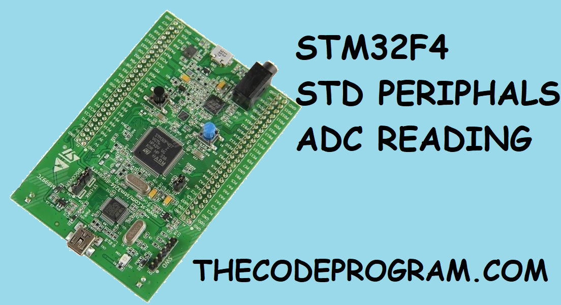
Hello everyone, in this article we are going to talk about how can we read analog voltage with STM32F407 with Standart Periphals and GPIO ports to read Analog values.First we need to have a STM32F407 processor or STM32F4-DISCO development board. Also we need uVision Keil installed on our computer, We are going to use a potantiometer to set the voltage level between 0VDC - 3VDC. STM32F407 has 3V ADC, arduino has 5V ADC. So we need to be careful to set maximum voltage value is 3V in our project.
So what can we do with analog voltage reading ?
We can read voltage value with ADC. Sometimes we need to use some potentiometers or LVDT's or something like that... in our project to decide position information. Thrust lever is the best example of this. Connect a potentiometer to the moving part of a thrust lever and when lever move voltage level will be changed.
Now Lets get started to code program. I will share all my code and explain part by part...
#include "stm32f4xx.h"                  // Device header


uint16_t ReadADC(void) //created a void to read ADC value
{
ADC_RegularChannelConfig
(
     ADC1,
     ADC_Channel_0, //which channel to get ADC value
     1,
     ADC_SampleTime_56Cycles //set reading cycle, decreasing this value will
     increase the reading speed.
);
	ADC_SoftwareStartConv(ADC1); // starts softwares of  ADC1 module

	/* wait for the state */
	while(ADC_GetFlagStatus(ADC1, ADC_FLAG_EOC) == RESET);
	return ADC_GetConversionValue(ADC1);
}


int main()
{
	uint16_t adc_data ; // we need min. 12 bit variable to keep  8 bitadc data.

	GPIO_InitTypeDef GPIO_InitStructure;
	ADC_InitTypeDef ADC_InitStructure;
	ADC_CommonInitTypeDef ADC_CommonInitStructure;

	//LEDS connected on the STM32F4-DISCO board
	RCC_AHB1PeriphClockCmd(RCC_AHB1Periph_GPIOD, ENABLE);
	RCC_AHB1PeriphClockCmd(RCC_AHB1Periph_GPIOA, ENABLE);

	// ADC 1 module connected to the APB2 bus. You can check stm32f4xx_rcc.c and line: 1599.
	RCC_APB2PeriphClockCmd(RCC_APB2Periph_ADC1, ENABLE);


	//STM32F4-DISCO board LED starting configurations.
	GPIO_InitStructure.GPIO_Mode = GPIO_Mode_OUT;
	GPIO_InitStructure.GPIO_OType = GPIO_OType_PP; // we did not specified as PullUp or PullDown. So it will be behave as Open Drain.
	GPIO_InitStructure.GPIO_Pin = GPIO_Pin_12 | GPIO_Pin_13 | GPIO_Pin_14 | GPIO_Pin_15;
	GPIO_InitStructure.GPIO_Speed = GPIO_Speed_100MHz;
	GPIO_Init(GPIOD, &GPIO_InitStructure);


	//ADC Pin configurations.
	GPIO_InitStructure.GPIO_Mode = GPIO_Mode_AN; // We specified as GPIO_Mode_AN to read analog data.
	GPIO_InitStructure.GPIO_Pin = GPIO_Pin_0;
	GPIO_InitStructure.GPIO_OType = GPIO_OType_PP;
	GPIO_InitStructure.GPIO_PuPd = GPIO_PuPd_NOPULL;
	GPIO_Init(GPIOA, &GPIO_InitStructure);


	ADC_CommonInitStructure.ADC_Mode = ADC_Mode_Independent; // We set the ADC Mode as Independent to work.
	ADC_CommonInitStructure.ADC_Prescaler = ADC_Prescaler_Div4; // We have set the prescaler value. Received data will bi divided by 4.
	ADC_CommonInit(&ADC_CommonInitStructure); //Started the above configurations.


	ADC_InitStructure.ADC_Resolution = ADC_Resolution_8b; // this means we are going to divide the value by 20mV.
	ADC_Init(ADC1, &ADC_InitStructure); //Set configuration of ADC1

	//Enable ADC1
	ADC_Cmd(ADC1, ENABLE);


	while(1)
	{
		adc_data = ReadADC(); // we will have a value between 0 and 255

// Here is the some LED shows according to fetched ADC value.
			if(adc_data < 50)
			{
				GPIO_ResetBits(GPIOD, GPIO_Pin_12| GPIO_Pin_13 | GPIO_Pin_14 | GPIO_Pin_15);
			}
			else if(adc_data > 50 && adc_data < 100)
			{
				GPIO_SetBits(GPIOD, GPIO_Pin_12);
				GPIO_ResetBits(GPIOD, GPIO_Pin_13 | GPIO_Pin_14 | GPIO_Pin_15);
			}
			else if(adc_data > 100 && adc_data < 150)
			{
				GPIO_SetBits(GPIOD, GPIO_Pin_12 | GPIO_Pin_13);
				GPIO_ResetBits(GPIOD,  GPIO_Pin_14 | GPIO_Pin_15);
			}
			else if(adc_data > 150 && adc_data < 200)
			{
				GPIO_SetBits(GPIOD, GPIO_Pin_12 | GPIO_Pin_13 | GPIO_Pin_14);
				GPIO_ResetBits(GPIOD,   GPIO_Pin_15);
			}
			else if(adc_data > 200 )
			{
				GPIO_SetBits(GPIOD, GPIO_Pin_12 | GPIO_Pin_13 | GPIO_Pin_14 | GPIO_Pin_15);
			}
	}
}
Now let me explain what I have done part by part:
uint16_t ReadADC(void) //created a void to read ADC value
{
	ADC_RegularChannelConfig(ADC1,	 ADC_Channel_0, //which channel to get ADC value												 	 1,
        ADC_SampleTime_56Cycles //set reading cycle, decreasing this value will increase the reading speed.
													);
	ADC_SoftwareStartConv(ADC1); // starts softwares of  ADC1 module

	/* wait for the state */
	while(ADC_GetFlagStatus(ADC1, ADC_FLAG_EOC) == RESET);
	return ADC_GetConversionValue(ADC1);
}
In this code block we have a function to read our ADC data from the pin that connected to variable voltage source. This source may be a potantiometer or a LVDT etc... with ADC_Channel_0, we have selected the reading channel of ADC hardware. ADC_SampleTime_xxCycles is a value to set the how many cycle need to be counted to read analog value again. So we can set the sampling time with this value. After making first configurations we are starting the software conversation and than waiting for the reading.
After creating this read method now we need to configure inside of main function. Lets get started to code main function.
GPIO_InitTypeDef GPIO_InitStructure;
ADC_InitTypeDef ADC_InitStructure;
ADC_CommonInitTypeDef ADC_CommonInitStructure;
Now we have three variables top of in main fonction. We will use these variables to configure and set our pins and ADC values.
//LEDS connected on the STM32F4-DISCO board
	RCC_AHB1PeriphClockCmd(RCC_AHB1Periph_GPIOD, ENABLE);
	RCC_AHB1PeriphClockCmd(RCC_AHB1Periph_GPIOA, ENABLE);

	// ADC 1 module connected to the APB2 bus. You can check stm32f4xx_rcc.c and line: 1599.
	RCC_APB2PeriphClockCmd(RCC_APB2Periph_ADC1, ENABLE);
In above code we are setting the which buses will be activated. If we forget this section our pins and hardwares will not work. Because these buses are providing oscilated wave and this keeps chips hardwares to work.
Now let me configure GPIO pins for LEDs and ADC.
//STM32F4-DISCO board LED starting configurations.
	GPIO_InitStructure.GPIO_Mode = GPIO_Mode_OUT;
	GPIO_InitStructure.GPIO_OType = GPIO_OType_PP; // we did not specified as PullUp or PullDown. So it will be behave as Open Drain.
	GPIO_InitStructure.GPIO_Pin = GPIO_Pin_12 | GPIO_Pin_13 | GPIO_Pin_14 | GPIO_Pin_15;
	GPIO_InitStructure.GPIO_Speed = GPIO_Speed_100MHz;
	GPIO_Init(GPIOD, &GPIO_InitStructure);

	//ADC Pin configurations.
	GPIO_InitStructure.GPIO_Mode = GPIO_Mode_AN; // We specified as GPIO_Mode_AN to read analog data.
	GPIO_InitStructure.GPIO_Pin = GPIO_Pin_0;
	GPIO_InitStructure.GPIO_OType = GPIO_OType_PP;
	GPIO_InitStructure.GPIO_PuPd = GPIO_PuPd_NOPULL;
	GPIO_Init(GPIOA, &GPIO_InitStructure);
In this section we have set the PD12, PD13, PD14, PD15 pins to the GPIO_OUTPUT. We are setting these pins. On the BOARD configuration these pins connected to the LEDs. These pins are setted as Open Drain.
Also In second section we have set the PA0 pin to analog hardware port. We will connect this pin to our potentiometer. We have set the mode to GPIO_Mode_AN.
In the last section we are using the adc_data variable to show LEDs. You can set these LEDs whatever you want.
So this is the end of the article.
Keep following my articles.
Have a nice coding.
Burak Hamdi TUFAN…


Comments
how many ohms for potentiometer ?
2024/05/27 20:13:16it is depending on your usage, as you have turned it it will change the voltage level to the analog input. I would recomend to use 5- or 10 kOhm. This should be good and safe to use.
2024/06/02 21:15:47